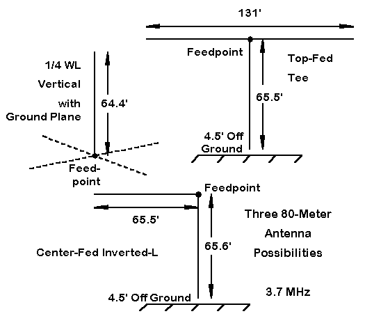
When I wrote on "The L-Antenna" for 10-meters a few months back, I noted that the antenna was not likely new. I have since learned that the basic idea seems to have originated with VK3AM in the early 1950s and is described in L. A. Moxon's (G6XN) classic HF Antennas for All Locations (pp. 154-156 of the first edition). This antenna is a standing L, although Moxon has no problems with viewing it inverted. Ralph Holland, VK1BRH, includes the L in his computer study of several antennas, including an interesting variant of the L: the 1/2 wl inverted-L. Perhaps the earliest article on the inverted-L as an all-band antenna may have been "The 'Inverted L' Ham Antenna," by Bob See, W5LTD, which appeared in Radio and TV News, January, 1959, pp. 64-65. Bob used base feeding to operate the antenna as a standard inverted-L monopole with a ground plane on 80 and as an end- or voltage-fed longer wire above 80, as his measured impedance figures attest. The 1/2 wl inverted-L can also be center-fed using parallel feedline and an ATU. We shall focus on the center-fed version: it is an antenna with excellent potential as an all-band substitute for the 135' center-fed doublet. The 1/2 wl inverted-L which we shall examine differs from standard 1/4 wl inverted-Ls in 2 ways: First, it is longer, of course. Second, it is normally current fed at the center (although end- or voltage-feeding is always possible, even if not always convenient). Hence, it can be viewed as an inverted Vee tilted over by 45 degrees. Alternatively, it can be viewed as a 1-leg-ground-plane 1/4 wl vertical upside down. If the upside-down vertical had a second leg going in exactly the opposite direction, the result would be--to a large degree--cancellation of the horizontally polarized radiation. Let's call this antenna the T. Both the L and the T differ from the standard 1/4 wl ground plane vertical by being complete antennas--dipoles as it were. Hence, neither requires a ground plane beneath them. For some situations, this fact can simplify construction. The figure below shows the structural differences among the three antennas for models set at 3.7 MHz. The L and T models were set at a top height of 70', with the vertical arm terminated 4.5' off the ground. Each antenna was modeled using #14 copper wire and average ground throughout.
Note that the inverted-L and the T present challenges to the builder in terms of
routing the parallel feedline to the top feedpoint. We shall do some
comparisons, but first, let's become a bit more familiar with the inverted-L
basic pattern.
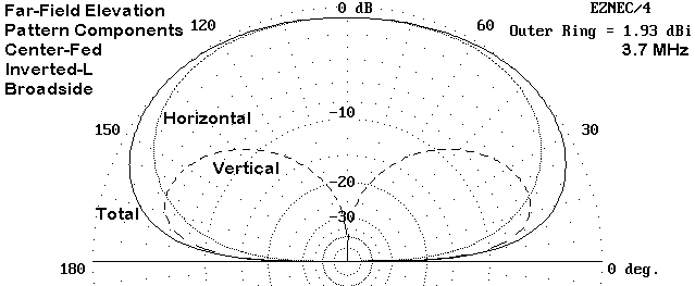
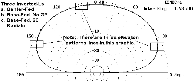
The elevation pattern above shows the vertical, horizontal, and total field components of the inverted-L radiation pattern taken broadside to the horizontal arm of the antenna, where radiation is strongest. In the plane off the ends of the horizontal arm, horizontally polarized radiation is somewhat weaker, but the vertically polarized radiation remains at full strength, with some pattern bending away from the horizontal arm.
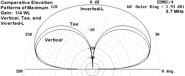
A fair comparison might be made among elevation patterns for the L, T, and
vertical. Since the total pattern of the L is a broad oval, let's take the
strongest direction also of the T, which happens to be off the ends of the
horizontal arms. The vertical is truly omnidirectional, so let's set at least 20
radials beneath it.
The comparative pattern above shows the rough equality of the T and the
ground-plane-vertical patterns under the specified conditions. Surprisingly, the
inverted-L comes close to both antennas in low angle radiation. It also has
stronger high angle radiation--without becoming a cloud burner--which is useful
for shorter skip contacts. In other words, the inverted-L has potential as an
all-purpose low-band antenna.
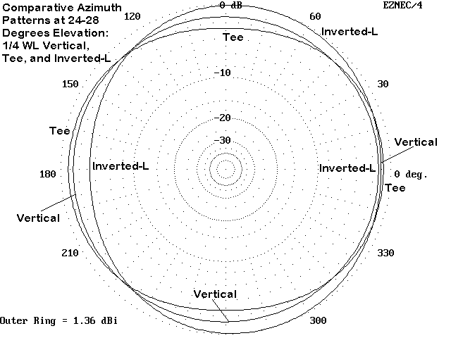
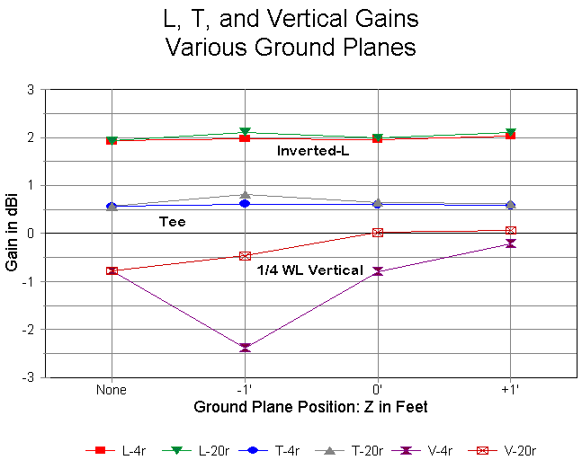
The azimuth patterns of the three antennas--taken at elevation angles between 24 and 28 degrees--show the slight oval of the T and the slightly more radical oval of the inverted-L. The L's azimuth pattern also shows the slight displacement in the direction away from the horizontal arm. However, these effects are small enough not to stand in the way of using the antenna for general operating purposes. The Ground-Plane Question In principle, as a complete 1/2 wl antenna, the inverted-L requires no ground plane. Likewise, the T should require none. In contrast, the 1/4 wl vertical requires a ground plane to complete the antenna. To test the relative need and utility of a ground plane, I modeled all three antennas with ground planes, first using 4 wires and then using 20 wires. I set each ground plane first at 1' below ground, then at the surface, and finally at 1' above ground. The vertical's source segment touches the ground, which gives erroneous results in NEC-4. Therefore, the surface ground plane for the vertical was set 0.1' above ground. The radial wires were the same length as the vertical radiators, which means slightly shorter radials for the vertical than for the L or T.
The antenna gains are compared in the graph above. The line connections between points are not real connections, but only let the eye tell which data points go together. As is evident, NEC-4 modeling strongly suggests that the addition of a ground plane adds virtually nothing to antenna performance for the inverted-L and the T, both of which we have described as complete antennas. In contrast, the vertical is dependent upon the most extensive (up to 60-100 radials) that a builder can install. (The vertical antenna data point for "No Ground Plane" should be used for reference and does not represent accurate data relative to a real antenna.) I further modeled the vertical with 64 radials. At a depth of 1', the antenna gain increased to 0.19 dBi, while setting them 1' above ground yielded a gain of 0.02 dBi. Modeling has consistently suggested that for perfectly symmetrical ground planes above ground, more than 6-8 radials may be superfluous. This conclusion does not necessarily apply to ground planes that are not perfectly symmetrical.
An alternative to high-altitude center feeding of the inverted-L is to base
feed it at the low end of the vertical. Models of this mode of feeding the
antenna show patterns quite consistent with those for center feeding, with a
source impedance in the neighborhood of 5000 Ohms. Once more, the addition of a
ground plane does not aid antenna performance in any way, as the following
elevation plot shows.
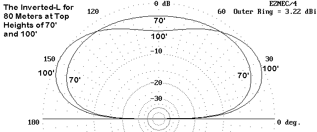
However, the absence of need for a ground plane should not be mistaken for an absence of a need for a good RF ground. In turn, we should not presume that the ground rod near the shack, which provides AC and DC power grounding for safety, also provides an adequate RF ground. Army tests established a couple of decades ago that a good RF ground needs periodic short (<2') rods connected by a perimeter wire or strap that essentially surrounds the entire station location. Installation Variations Knowing that not everyone tempted to use the inverted-L will have all of the space needed, I checked some variants that represent typical construction compromises or changes. Since the antenna will be fed with parallel transmission line, matching is not a major problem. However, changes of gain and elevation angle may indicate that some variations are better than others. 1. Height: elevating the inverted-L is a route to slightly more gain and a lower take-off angle broadside to the horizontal arm. Here is a table of values modeled with top heights at every 5' from 70 to 100 feet up.
Nothing drastic happens between any two levels, but the trends are clear.
Gain increases and take-off angle decreases. The antenna plays shorter, the
higher we go. However, unless one plans to use a monoband coax feed system, the
precise dimensions are not at all critical.
The elevation patterns in the figure compare the antenna at 70' and at 100' and add visual confirmation of the conclusion drawn from the table. 2. Sloping and Bending: The more normal problem for home installation is too little vertical or horizontal space. As the figure below shows, there are a number of installation "tricks" we might use. The question at hand is how much each will hurt performance.
Bending the vertical at the bottom: The first way to save vertical space or to protect family members from the high voltage at the antenna element end is to bend the lower end of the vertical to the side. The upper horizontal arm remains 65.5' long. The overall length of the vertical is also 65.5', but part is now vertical and part horizontal. I tested three scenarios, listed in the table below: The chief effect of the bend is to raise the high angle radiation strength a small bit and to raise the elevation angle of maximum radiation. The latter figure indicates a slight loss in the lowest angle radiation, which one would anticipate from shortening the vertical length. None of these small changes in dimension affect the usableness of the antenna. Sloping the horizontal arm down: One might wish to use the antenna where there is only one truly tall support and the support for the far end of the horizontal arm is lower. The result is a sloping horizontal arm. Using a peak height of 70' and keeping the dimensions of each wire at 65.5', I tested 2 scenarios, representing two degrees of slope, against the standard installation. Gain increases are at high angles of radiation, with some loss of low angle radiation strength. Although a true horizontal is perhaps the best compromise for maximum low and high angle performance, the patterns with a modest slope to the horizontal arm do not make the antenna unusable by any means. Bending the horizontal arm far end down: If horizontal space is limited, a common practice is to bend (or dangle) the outer ends of a dipole downward. since the region is the high voltage and low current portion of the antenna, the radiation pattern is least affected by modifying the geometry. Again, I compared 2 scenarios to the full length horizontal arm configuration. Low angle radiation remains essentially constant, since the vertical arm has not been altered. Further shortening of the horizontal arm would show a gradual further reduction in maximum gain and in the take-off angle. Higher-angle radiation is decreased, although the antenna remains eminently usable. Like many wire antennas, the inverted-L will tolerate moderate alterations of geometry to fit the space available and still yield good, if not peak, performance. Multi-Band Use of the Inverted-L One disadvantage of the 135' horizontal doublet when used on the upper HF bands is that the pattern breaks into a collection of fairly narrow lobes with deep nulls between them. Since the nulls change position from band- to-band, the user is often surprised to discover that signals from certain directions are weaker than expected. The inverted-L, when fed with parallel transmission line and an antenna tuner, is not wholly exempt from this phenomenon. However, since one arm is fully vertical, the nulls tend to be much shallower. At the same time, gain peaks are less pronounced. Even harmonics of the antenna's fundamental frequency show high impedances,
in some cases with a high reactive component. The WARC bands show more moderate
impedances at the antenna feedpoint. Use of 450-Ohm or 600-Ohm parallel feedline
is recommended in order to provide reasonable values of impedance at the antenna
tuner terminals. As with all such antennas, if a tuner seems unable to effect a
match on a given band, adding a short section of feedline between the existing
line and the tuner output terminals will often correct the situation.
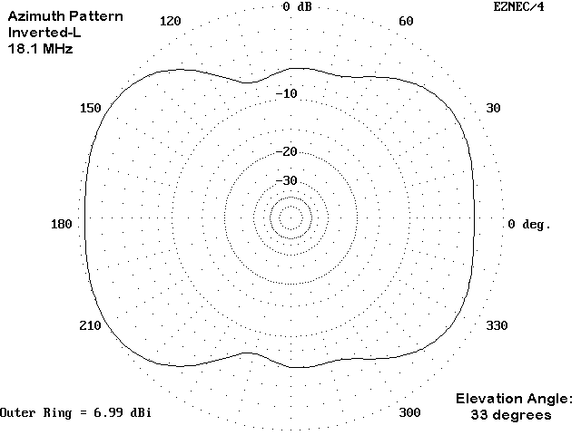
The annotation "square" to describe the azimuth pattern is illustrated by the
18.1 MHz pattern. On this band, the strongest signal occurs at the second
elevation lobe. There is a usable but less strong lobe at about 16 degrees
elevation. Note the absence of sharp nulls and lobes.
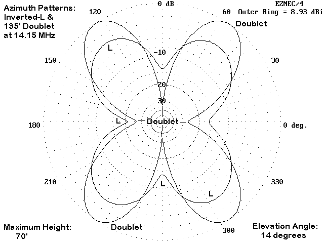
Even where lobes and nulls do occur, both are much less pronounced than they are with a standard doublet. The figure shows the differences for the 20-meter band. Doublet nulls exceed -25 dB relative to the lobes, whereas inverted-L nulls are under -10 dB relative to the lobes, which are also broader than those of the doublet. Of course, peak gain of the lobes is about 4 dB less than for the doublet lobes. For some types of operation, but certainly not for all, the absence of strong nulls can be more advantageous than a few extra dB of gain in very specific directions. The 100' Center-Fed Inverted-L Many hams who cannot erect a full 135' long inverted-L can often manage a 100' version of the antenna. This length would require 50' of horizontal run and about 55' of height to place the vertical section at least 5' off the ground. As we have seen, higher installations will yield better results, but the present values will provide a kind of worst-case scenario for modeling that antenna. Since the sketches for this shortened version of the inverted-L, which is about 70% full size at 80 meters, would be the same as those for longer versions, we can jump directly to a table of values for multi-band use of the antenna. As one might expect, the shorter antenna breaks into multiple lobes more slowly with increases in frequency. Moreover, the pattern of high and low feedpoint impedances differs greatly from the pattern for the 135' version. Given the lower top height, the elevation angles of maximum radiation are somewhat higher, especially on the lowest bands of operation. (Note that the band on which an unexpected high angle of maximum radiation occurs for both versions also shows a lobe of nearly the same strength at a lower angle--just about 20 degrees lower. Hence, useful radiation occurs on that band--in this case 17 meters.) Shorter antennas--down to about 90' overall wire length can be built and used on 80 meters. Below about 90' overall wire length, the antenna becomes essentially a 40-meter-and-up inverted-L. Conclusion The center-fed inverted-L has the potential to be a quite satisfactory all-band wire antenna suited to certain environments. The length can be almost anything about 3/8 wl or longer for the lowest frequency of intended operation. Although the overall gain will be lower for each band than the gain of a horizontal doublet using the same overall wire length, the elevation angle of maximum radiation for the L will be lower than for a doublet with the same top height. There is little evidence, despite the vertical position of one arm of the antenna, that the inverted-L would benefit from a ground plane beneath the antenna. The actual low-angle gain of the inverted-L will, however, vary with the quality of the soil in the region of reflection at a distance from the vertical arm. All patterns were taken over average soil, and soils that are either poor or better than average will tend to show a higher gain and lower take-off angle, at least on the fundamental frequency. The electrical lineage of the center-fed inverted-L is from the dipole by way of the inverted-Vee. For the amateur yard that is short on horizontal space but long on tall supports, the inverted-L may be the antenna of choice as an all-band wire--whether used as the primary station antenna or as the back- up for more complex arrangements. Use the formula: 492/fMHz (259.4 @ 1.9MHz for example) to find the overall length of the aerial, which is composed of H (Horizontal) + V (Vertical) components. Try to get the vertical section as tall as possible, since the current distribution is maximum at the midpoint of the aerial (129.7 Ft @ 1.9 MHz). It can provide good radiation from both H and V components. The H component can slope down (or up), but this tends to skew the max radiation towards the direction of slope, which is sometimes desirable. For instance: working VK/ZL, JA, Africa, or Europe. The overall best advantage of the aerial is that only a minimum ground is needed unlike the 1/4 wave version. Make for 160, 80, 40, or 20 meters with the appropriate single-band L-network. Patterns vary per band if actually cut for 160, then used also on 40 or 80. 40 is good off the ends; 80 is good broadsides and vertical at the same time (more so than on 160). Use a tunable L-Network or any antenna tuner capable of matching high impedance loads, and it can be a good multiband system.
|
