|
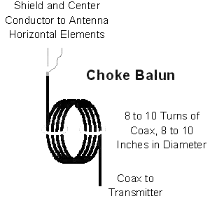
The G5RV is a balanced antenna fed with a balanced 450 ohm line. When feeding this antenna with an unbalanced line (such as coaxial cable), it is a good idea to use a 1:1 choke BALUN at the coax to feedpoint connection. The balun will reduce or eliminate parallel currents on the outside of the coax shield. This will prevent or reduce RFI, RF feedback, RF burns, and other effects of excessive RF in the station. The best balun for this antenna is an air-core choke balun. Avoid using other types of baluns, such as ferrite sleeve or transformer type baluns. This antenna has a high reactive component at the feedpoint SWR of more than 2:1. The high SWR increases loss in ferrites and may cause excessive core heating, core saturation, or arcing in the windings. The air wound balun required for a center-fed antenna with 450-ohm ladder line can be constructed by winding the coaxial feedline cable in a single-layer solenoid coil with at least 10 turns of 4 to 6 inch diameter. One source suggest 10 turns wound on a 10-inch diameter form. The turns can be taped or secured by nylon cable ties. The balun can be wound on PVC pipe or any other non-metallic form. Place the balun immediately at the point where the feedline leaves the air (for 160 meter operation) or at the feedpoint connection (if the antenna is only operated on 80-10 meters). The feedline shield should not be grounded on the antenna side of the balun. Warning: The balun should be kept away from any conductive material.
General description A balun is a device that joins a balanced line. It may have two conductors, with equal currents in opposite directions, such as a twisted pair cable to an unbalanced line. Or, it may have just one conductor and a ground, such as coaxial cable. A balun is a type of transformer - it is used to convert an unbalanced signal to a balanced one or vice versa. Baluns isolate a transmission line and provide a balanced output. A typical use for a balun is in a television antenna. The term is derived by combining balanced and unbalanced. In a balun, one pair of terminals is balanced, that is, the currents are equal in magnitude and opposite in phase. The other pair of terminals is unbalanced; one side is connected to electrical ground and the other carries the signal. Balun transformers can be used between various parts of a wireless or cable communications system. The following list illustrates some common applications.
Baluns can also provide impedance transformation in addition to conversion between balanced and unbalanced signal modes - others provide no impedance transformation. For 1:1 baluns (no impedance transformation), the input and output are usually both 50 ohms or 75 ohms. The most common impedance-transformation ratio is 1:4 (alternatively 4:1). Some baluns provide other impedance-transformation ratios, such as 1:9 (and 9:1), 1:10 (and 10:1), or 1:16 (and 16:1). Impedance-transformer baluns having a 1:4 ratio are used between systems with impedances of 50 or 75 ohms (unbalanced) and 200 or 300 ohms (balanced). Most television and FM broadcast receivers are designed for 300-ohm balanced systems, while coaxial cables have characteristic impedances of 50 or 75 ohms. Impedance-transformer baluns with larger ratios are used to match high-impedance balanced antennas to low-impedance unbalanced wireless receivers, transmitters, or transceivers. In order to function at optimum efficiency, a balun must be used with loads whose impedances present little or no reactance. Such impedances are called "purely resistive." As a general rule, well-designed communications antennas present purely resistive loads of 50, 75, or 300 ohms, although a few antennas have higher resistive impedances. The "balanced" terminals of some baluns can be connected to an unbalanced system. One terminal of the balanced pair (input or output) is connected to ground, while the other is connected to the active system element. When this is done, the device does not operate as a true balun, because both the input and the output are unbalanced. A balun used in this way has been called an "un-un" (for unbalanced-to-unbalanced). Some baluns can work as an impedance transformer between two unbalanced systems if there is little or no reactance. But certain types of baluns do not work properly when connected in this manner. It is best to check the documentation provided with the device, or contact the manufacturer, if "un-un" balun operation is contemplated.
|