|
The Bead Balun
Andy Griffith - W4ULD
Ferrite beads hsve been used by
Hams for quite a few years to “knock” the RF off of
computer cables and other lines. Ferrite beads over coax
also make an effective 1:1 current balun by preventing
the flow of RF currents along the outside of the coax
shield. The bead balun amounts to one turn on the core.
One advantage of the bead balun installed over coax is
that the impedance of the line is not changed.
Like toroid cores, beads come in
many sizes and material values. Probably the best
material for HF through UHF is equivalent to Amidon
material 43. Fortunately, all of the beads I have
purchased at Hamfests or ordered from surplus houses
have been very similar to material 43.
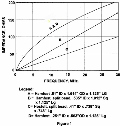
The impedance of a single solid
bead over coax starts relatively low at 1.8 MHz. but
climbs rapidly with frequency (See Figure 1, A & D).
Amidon shows 43 material peaking in impedance at about
200 MHz. and still having relatively high impedance as
high as 1000 MHz. Thus, we can use 43 material beads for
RF suppression and baluns throught the amateur radio
spectrum.
Two beads available at Hamfests and
surplus houses are shown as A & D in Figure 1. My
reliable impedance measurements are limited to about 30
MHz. D in Figure 1 is for a common bead which is .251
in. ID x .563 in OD x 1.125 in. long. This bead fits
nicely over RG-8X coax. A in Figure 1 refers to a larger
bead which will fit over RG-213 type coax.
Ten of these or the smaller beads
stacked in series on coax shows good balance in the HF
spectrum from 1.8 to 30 MHz. I have compared bead baluns
with other 1:1 baluns in operating situations and find
no difference among them.
Split beads which can be opened to
“snap” over the coax are also available at Hamfests and
on the surplus market. While these are convenient, their
effectiveness is less than half that of the solid beads
for a given ID and volume of ferrite in the HF bands as
can be seen from B and C in Figure 1. Large bead B had
about 1-1/2 times the ferrite of solid bead A.
Some of you may remember the 2
M/440 antenna project that CCARS sponsored a few years
ago. In this case a single “snap on” bead like B in
Figure 1 was an adequate balun for 144 and 445 MHz. Note
that in the HF spectrum the split beads follow a
straight line relationship between impedance and
frequency. It appears that the split beads become more
efficient at frequencies above HF.
While not related to baluns, split
beads are most useful for Hams using HF mobile rigs.
Beads placed over battery cables and coax to the antenna
can prevent RF in the cab from interfering with
operation of the transceiver and the auto’s computer.
Usually such problems are a result of an inadequate RF
ground to the chassis of the vehicle. This problem
should be tackled first.
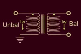
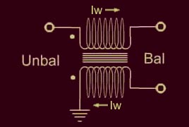
Bead Balun Concepts Comparison
Balun Bandwidth The type of balun used depends on what you want to achieve and what bands you are working. If you are going for maximum coverage of bandwidth, you will not have an antenna as good on one particular frequency but a wide bandwidth balun is best.
If
you are looking for maximum signal using a Narrow Mode such as CW or
SSB, it is pointless using a wideband antenna (ergo balun) in which case
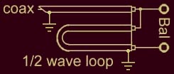
a narrow bandwidth balun is best. Type of Balun to use - Voltage or Current The best balun to use is the one that does the job with the least loss, of course. On 6m and above, most generally use a dedicated antenna. A ½ wave loop made of RG-214 has an insertion loss of roughly 0.03db and so is the lowest loss balun I could find. This is a voltage balun. A common mode choke (ugly balun) - current balun - wound with RG-58 using the recommended lengths has a loss of roughly 1.2db. In addition, some sort of impedance matching may be needed so a voltage balun is the only real alternative. On HF, a wide bandwidth is desirable. Voltage baluns are either too big or too inefficient. If you use a tuner, that does all the impedance matching necessary so a simple current balun after an unbalanced tuner has the lowest insertion loss. In this situation a current balun is best.
If a wound balun with impedance
matching is needed, the auto-transformer types are generally more
efficient. Winding coils with coax There are situations where winding coils with coax is useful but there are some strange misconceptions. The centre conductor is surrounded by a good conductor that contains any magnetic or electrical fields it (centre) produces. The inner conductor therefore produces no magnetic effect whatever in the coil or any former it is wound on unless it is by currents it induces in the outer.
Coils of coax around a former do
not constitute a transformer. They form a choke on the outer conductor
only. Voltage baluns using coax The ½-wave length coax balun is highly recommended where it can be used (usually impractical on HF). This is a very low loss balun.
Core-type current balun Highly recommended. This is a very low loss balun and ideal for use with a tuner.
I tried but was unable to measure
any insertion loss associated with either the bolt or the toroid former
(powdered iron) for working currents. There was some but the meter
needle was so close to the same value in and out I really could not say
what the loss is. As soon as I have the time, I will measure the
impedance to common mode currents with various formers. Common mode choke or ugly balun Not recommended. There are better ways of achieving the same effect. This type of balun is one of the easiest to make but more difficult to explain. It would be easiest to build up a picture. Consider first, the following situations.
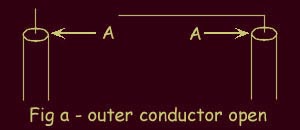
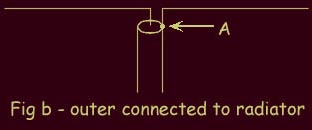
Figure (a) shows the situation where the outer conductor is not connected to anything. It doesn't matter what happens with the inner conductor, there can be no current at point A because it isn't connected. Current must have at least some place to flow. Where a single radiator is present like this, the electric field on the inner tries to work against the coax outer and produces common mode currents that simply heat the coax. Figure (b) shows the situation where the outer conductor is now connected to a radiator. In this situation, there are still commom mode currents. The coax shield is a pseudo ground and isn't trying to push any current anywhere. With unbalanced line it is only the inner that is driven. The coax shield only conducts working currents because they are pushed by the inner. The electrical field created along the radiator connected to coax centre is partly working against the coax.
Figure (c) shows the situation where the coaxial cable is wound into a choke. A choke is nothing more than a BIG inductance. An inductance resists a change in current both magnitude and direction. As frequency increases, the impedance increases. At Radio Frequency the impedance is so big, neither induced current can pass through it except for the working currents on the inside of the shield. Point A can have currents induced by the electrical field in the radiators but this current can't pass through the choke and to ground.
I have called called it a ½ common
mode choke instead of an ugly balun because it affects the outer
conductor only. Because both the magnetic and electrical fields
generated by the inner conductor are contained within the coax, they are
unaffected and thus the currents in the inner conductor are unaffected. Another way to do it More ferrite is usually required than two pieces but you get the idea.
|