|
A recent posting on the Extended Double Zepp under the title "Wanna Double your power for free?" brings to our attention an interesting wire antenna. However, it leaves out a few points that are important in understanding the antenna and deciding if you want to build one. First, the antenna is non-resonant, that is it does not operate at a point at or near zero reactance. Being about 1 1/4 wavelengths long, it will have high capacitive reactance at the feedpoint. Hence, the need for stub tuning for single band use or parallel feedline for either single- or multi-band use - the latter is usually much simpler. Second, because the antenna is non-resonant, the "formulas" for cutting one are not nearly so precise as with a resonant antenna. In fact, they come from an old and perhaps outdated habit of amateurs to try to reduce antennas to a series of cut-to-formula-and-forget exercises. In fact, the 600/F formula for each leg may give you higher than necessary reactance. As an exercise, I modeled an EDZ for 20 meters at 35' up (that is a half wavelength up). I used the formula and then lengthened the legs twice and here is what I got for feedpoint impedances. Leg
Gain R+/-jX
Beamwidth Note that both the R and the X go down as we lengthen the antenna away from the very high R and X of a 1 wavelength antenna. Exact figures will vary with the antenna height in fractions of a wavelength above ground. Notice that we pass the point of absolute max gain to get the lower resistive and reactive components, but 0.1 dB difference will never be detectable in any operating situation. Third, the price of gain in a bi-directional antenna is beam width, and this is a serious consideration for anyone contemplating this antenna. The beam width (signals down by 3 dB relative to the point of highest signal strength) for a dipole on 20 at 35' is about 88 degrees, and the pattern is a big peanut. Your orientation need only be approximate to hit a broad swath of stations, like all of Europe, etc. The beamwidth of an EDZ is in the 30s, as the chart about shows. That's a lot narrower than most long Yagis. You will have to decide within fairly narrow limits just where you want your antenna to point and hope that both sides are doing some useful work. This might be for some Europe off one side and VK-ZL off the other; for others, it might be over the poles; for still others, the off side pointing "nowhere" may be the ticket to reduced QRM for the on side. If you live in Texas and broadside a dipole up to the US, you will work from coast to coast, although AZ and FL may be off the sides. If you do the same with an EDZ, you will Work All Minnesota in a week and wonder where the east and west coasts have gone. The quartering side lobes of the EDZ are a good 10 dB below the main lobe, which puts them about 7 dB below the quartering angles from a half-wavelength dipole. So learn all you can about an antenna and do not jump at one just because it promises gain. Gain is cheap. Getting an antenna to put its gain and other properties just where you want them to go gets expensive - whether in money or time or energy. Best of all, the EDZ beam produces
patterns that look like faces with interesting ears -- antenna
modeling is full of surprises, and not all of them are
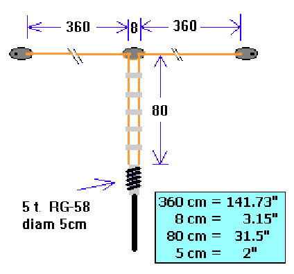
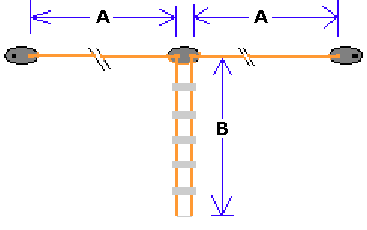
technical. Extended 6-Meter Double Zepp This is a very inexpensive and easy antenna to build and has been used for many years in Europe by 6 meter operators with great success. The short feedline wires should be separated about 3 inches from each other with the spreaders spaced evenly apart down the short length of feedline leading to the coax 1:1 balun coil. The lower end of the homemade ladder line is soldered with one side to the center conductor and the other side to the screen or shield of RG58 coax going to your radio and sealed. This coax is close-wound with 5 turns, forming a 1:1 balun, on a piece of 2" PVC pipe and secured tightly, before it is routed down to the transceiver. Make sure to seal the connections between the coax and the wire elements. As with any homebrew antenna project, check the SWR using low power and trim or add to each top half for lowest reading.
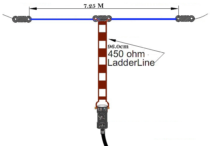
Six meters is hot, and when six is open, all you need is a good horizontal antenna to work long-distant "skip" stations. Enjoy MAXimum flat-top gain on Six meters with this horizontal antenna. Since most single-sideband is horizontally polarized, the BUXCOMM MAXSIX will meet them, "head-on." This version of the 6 Meter Extended Zepp antenna is designed for 50 ohm coax feed. The elements are made of high-tensile strength antenna wire, It is super flexible by using 41 strands of silver-flashed copper. The short section of ladder-line is part of the transmission line transformer (TLT) that transitions the impedance between the BUXCOMM VBALUN and the impedance at the feed-point of this antenna.
The total length of the BUXCOMM Double-Zepp is approximately 25 feet. This length represents a 1.28 wavelength for a Double-Zepp for six meters. We have constructed all the main connections and weather-proofed them so your effort installing the MAXSIX will be minimized. The center insulator is a block of fiber-glass chosen for its strength and insulation qualities at VHF. Be sure to use CS 104 CoaxSeal to seal the connections between the coax connector and the VBALUN. As with any antenna project use caution, and read the precautions shown at the top of this page. The length of the ladder-line is calculated for
the middle of the six meter band, or approximately 52.5 Mhz. In
addition, the elements are cut for this section of the six meter
band. This Six meter (MAXSIX) Extended Double-Zepp antenna and
BALUN will handle 750 watts SSB. At FSK, SSTV, or PSK the RMS power
should be reduced to 200 watts.
|


