|
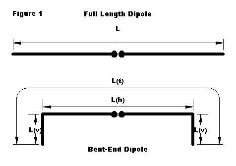
We have taken a look at the basic resonant half-wavelength center-fed dipole antenna constructed at low heights (relative to a wavelength). However, the antenna was too perfect: we stretched it out full length horizontally. This is its most desirable form. But what do we do if we cannot quite fit a dipole into the space we have. Before we jump into the box marked "loading coils," let's consider some less lossy alternatives. In general, unless we turn the antenna into a piece of origami, the losses will be less than those of a helical dipole. Option 1 - Bend the ends If you cannot fit the full dipole in your space, bend the ends, usually at right angles, and usually down. The "right angle and down" technique results from the absence of additional high supports - hence, the ends just drop. First, do not just drop the ends near and parallel to a metal end support pole. The close coupling will likely detune the antenna severely. Second, consider angling the excess length in a slope to a house top, tree, or other support that is lower. Since we cannot cover all the possibilities, let's look at the drooping-end version, pictured in Figure 1. Do I lose anything? If so, what? How far can I shorten the horizontal part of the antenna before I lose too much? What happens to the overall wire length?
Here is a table of what happens to the resonant length of an 80-meter dipole at 35' when the ends are bent downward: Size L(h) L(v) L(total)
Full 131.4' -- 131.4'
92% 121' 5.55' 132.1'
84% 111' 10.9' 132.8'
77% 101' 16.1' 133.2'
69% 91' 21.3' 133.6'
As you can readily see, the coupling of the vertical and horizontal lengths at the corners requires a gradual lengthening overall. The wire grows longer with the shortening of the horizontal section because the current, fields, and coupling all grow stronger. Not only does the antenna get longer, its gain in dBi at a fixed elevation angle decreases. For an elevation angle of 45░, the decrease in broadside gain and in front-to-side ratio in dB look like this: Size 45░ F-S Feedpoint
Gain Ratio Impedance
Full 3.93 3.85 54.7 ohms
92% 3.88 3.74 54.4
84% 3.75 3.45 53.7
77% 3.51 3.03 52.4
69% 3.16 2.52 50.9
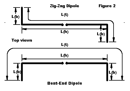
As the horizontal portion of the antenna is shortened and more hangs down at a lower height, the gain of the antenna drops. The drop is more precipitous as the antenna grows shorter horizontally. Also decreased is the antenna's directivity. The front-to-side ratio drops ever more rapidly as the horizontal section grows shorter. These properties are functions of antenna shape and would apply proportionately to bent dipoles for any HF band. There are alternative ways to bend dipole ends, shown in Figure 2.
Simply bend the ends of the dipole horizontally, either in the same direction of in a zig-zag form. Gain and front-to-side ratio hold up much better, although when the ends of the zig-zag version exceed 20' each, the pattern takes a tilt away from the bent ends. Here are the tables corresponding to those of the vertically bent dipole, carried one increment of shortening further. Separate figures are given only where significantly different. Size L(h) L(b) L(total)
Full 131.4' -- 131.4'
92% 121' 5.55' 132.1'
84% 111' 11.0' 133.0'
77% 101' 16.3' 133.6'
69% 91' 21.65' 134.3'
62% 81' 27.0' 135.0'
Size 45░ F-S Feedpoint
Gain Ratio Impedance
Full 3.93 3.85 54.7 ohms
92% 3.92 3.82 54.0
84% 3.87 3.75 52.3
77% 3.80 3.63 49.3
69% 3.72 3.45 45.1 *
3.56 45.6 **
62% 3.56 3.22 40.9 *
3.65 3.46 41.5 **
* = horizontally bent dipole
** = zig-zag dipole
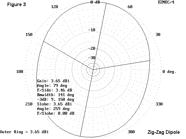
All of the dipoles have maximum gain broad side to the main horizontal wire except for the last two models. The 69% zig-zag model (134.3' total) is 7° off broadside, while the 62% zig-zag model (135' overall) is 11° off broadside, both away from the inside bend. Elevation patterns are unaffected by the bends.
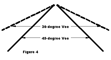
In many ways, horizontally bending or zig-zagging a dipole is superior to vertically bending the antenna. At any height, horizontal bends tend to preserve both gain and directivity. The cost is a more rapid decrease in the feedpoint impedance. In the end, decreasing the main wire run below about 60% of full size decreases gain ever-more rapidly, especially for versions of the antenna with the ends bent in the same direction. The zig-zag bend is more immune to this effect because its bends produce less field cancelling. Bending or zig-zagging a dipole at angles that are neither purely horizontal or purely vertical will produce intermediate values of both feedpoint impedance and gain. Moreover, the ends do not have to be bent in precisely equal amounts or angles. And, you may have more than one bend per leg. The antenna will still perform reasonably well as a dipole. As with the vertically bent dipole, the results of these 3.6 MHz models can be extrapolated for dipoles on any HF band. When performing any extrapolation, remember to adjust for height differences in terms of fractions of a wavelength, using the graphs in an earlier installment as a guide. Although we shall look at center-fed multiband dipoles in another installment, we should note here that any of these 80-meter dipoles may be fed with 300-ohm or 450-ohm parallel feedline and an antenna tuner (ATU). Expect azimuth patterns to vary from the norm for straight wires as the frequency goes up and the bent portions become more significant portions of a half wavelength. Option 2 - Make an inverted Vee Although many folks think of the inverted Vee antenna as relevant just to situations where there is only one hanging point in the yard, the Vee is also a space-saving antenna. Drooping the wires 30░ produces a horizontal dimension only 87% that of a full length dipole, while drooping the wires down to 45░ shortens the length along the ground to about 70% of that required by the truly horizontal dipole.
Some purists claim that an inverted Vee is not an inverted Vee unless the element slope is 45░. Actually, the inverted Vee is any antenna whose elements have appreciable downslope. Whatever the actual angle, the Vee has all its length below the feedpoint. Therefore, it is important to mount the Vee as high as possible. One way to equate the height of antennas of roughly comparable polarization but different geometries is to find the heights that give equal angles of maximum radiation. So how do the Vee and the standard dipole compare?
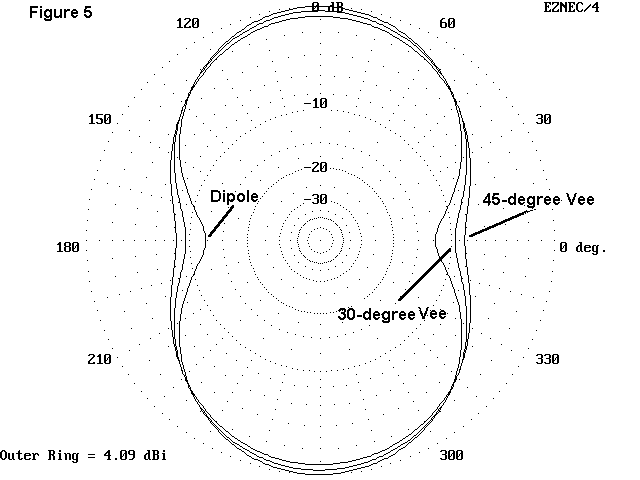
Figure 5 can be either informative or confusing, depending upon how carefully we read it. It summarizes the performance at a 20░ elevation angle of comparable dipoles and Vees. The following tables specify the antennas and why they are considered comparable. Ant. Dipole V-30░ V-45░
Height 51' 40-57' 35-59'
L (wire) 67.25' 67.9' 68.4'
L (horiz) 67.25' 58.6' 48.7'
Feed Z 86.6 ohms 71.5 ohms 53.3 ohms
Gain at
20░ el. 4.09 dBi 3.75 dBi 3.32 dBi
Front-to-side
Ratio 12.4 dB 9.2 dB 7.5 dB
Angle of Max.
Rad. 38░ 38░ 38░
In this table, I have chosen equal angles of maximum radiation as the basis of comparison. To obtain the angle of a dipole at 51', the 30░ Vee must have a peak height of about 57', about 11% higher than the dipole. The 45░ Vee must be about 16% higher it is apex, with a peak height of 59'. As one might expect, the 30░ Vee more closely approaches the dipole in all performance characteristics than does the 45░ Vee. With low wire antennas, the gain at the angle of maximum radiation is seldom a good measure of the antenna's working performance. Hence, Figure 5 displays the patterns at 20░ elevation, closer to the angle needed for long distance communications. Reading the gain figures from the table might leave the impression that the Vee is quite deficient compared to the dipole. However, the azimuth patterns demonstrate that there is less operational difference among the antennas. The dipole gain is only slightly higher than that of the Vee with a comparable take-off angle. Where the dipole shines is in its directivity, which will be a boon to some, the bane of others who desire all-direction communications. Evaluating the Vee vs. the dipole at other heights requires that one adjust all three antennas by roughly equivalent amounts. Likewise, extrapolating these modeling results for other bands will require adjustment in terms of fractions of a wavelength above ground. The dipole at 51' height is about 3/8 wavelength above ground. If we were to use a certain maximum antenna support height as the basis for our comparison, the Vee would appear to be an inferior performer. For the exercise, let■s compare a 45░ Vee and a dipole, each with a maximum height of 35' and resonant at 7.15 MHz. The data table would look like this: Antenna Dipole V-45░
Height (max.) 35' 11.2-35'
L (wire) 66.35' 67.36'
L (horiz) 66.35' 47.7'
Feed Z 83.9 ohms 51.4 ohms
Gain at
20░ el. 1.61 dBi -1.22 dBi
Front-to-side
Ratio 10.5 dB 2.6 dB
Angle of Max.
Radiation 60░ 90░
First, do not be put off by the negative gain figure for the Vee. At a 20░ elevation angle, it will be about 3 dB or half an S-unit less sensitive (or powerful from the transmitting point of view). Compared to many successfully used mobile antennas, the Vee will be a superior performer-- just not superior to a dipole with the same peak height. Second, notice that the Vee takes up less than 48' of linear space in the yard, compared to the dipole's 66+ feet. And, of course, a Vee needs only a single high support, with 2 end supports.
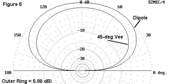
Figure 6 shows the elevation patterns for the two antennas along the axis of maximum gain for each (broadside to the wires). This graphic shows the Vee with the same maximum height as a dipole to be the lesser performer at all elevation angles. The question is this: when does it make sense to live by this pattern plot? The simple answer is this: if you have two supports more than 67' apart and each 35' tall or taller, then by all means, go for the dipole. Of course, you can also opt for some other antennas that need two supports 67' apart and that we have not looked at yet. On the other hand, if you have only one support, centered in the antenna area, then the Vee is for you. Option 3 - Slope your dipole There is no rule that says you cannot slope a dipole as needed to meet the levels of available supports. Nothing significantly bad happens if a dipole is closer to the ground at one end than the other. The imbalance created by having one end higher than the other is little more than the imbalance created because we cannot measure long pieces of wire accurately when they are stretched out on the grass. We already know that if we have a certain maximum height for wire support, the sloping antenna will have less gain that the flat-top version, but what happens if we align their center feedpoints and tilt them? Let's compare a flattop with a 30° and a 45° tilted antenna. And let's use a 30-meter dipole at 35' for the comparison. Ant. Flattop Tilt-30░ Tilt-45░
Height 35' 23-46' 18-52'
L (wire) 47.45' 47.45' 47.45'
L (horiz) 47.45' 41.09' 33.55'
Feed Z 87.2 ohms 82.5 ohms 78.9 ohms
Gain at
20░ el. 3.78 dBi 3.29 dBi 2.65 dBi
Angle of Max.
Rad. 39░ 37░ 34░
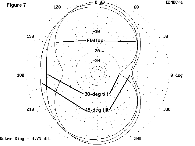
There is not much difference among the three antennas. Figure 7 shows that tilting the antenna puts an odd pinch in one side, but the main lobes are reliably broadside. The flattop does have higher gain at higher angles, and would thus be superior for shorter range communications by about a half S-unit.
The bent, folded, and mutilated dipole is still a dipole and still the heart
and soul of amateur radio. If it will not fit straight, bend it. The only way it
won't work is rolled up in a tight ball. |
