|
Louis Varney's "G5RV" was and is not an antenna, that is, an array of elements. It is an antenna system including a radiating element and a length of transmission line designed to present a "correct" impedance at a design frequency. The 1984 RADCOM Version of the Antenna SystemThe most familiar part of the system is the wire: a center-fed doublet 102' long. Actually, Varney calculated the length to be 3/2 wavelengths long at 14.15 MHz using a long standing equation:
The letter 'n' is the number of half wavelengths in the antenna. The result is 102.57' or 31.27 m. It is interesting that Varney notes in his 1984 article in RADCOM that he can shorten the wire to 102' or 31.1 m, since the entire system will be handled by an antenna tuning unit (or ASTU--antenna system tuning unit--as Varney preferred). (The entire 1984 article has been reprinted in Erwin David, G4LQI, HF Antenna Collection, published by RSGB in 1991. In the G5RV article, the author makes reference to his initial 1966 presentation of the basic idea. An adapted version appears in The ARRL Antenna Compendium, Vol. 1, 1985.)
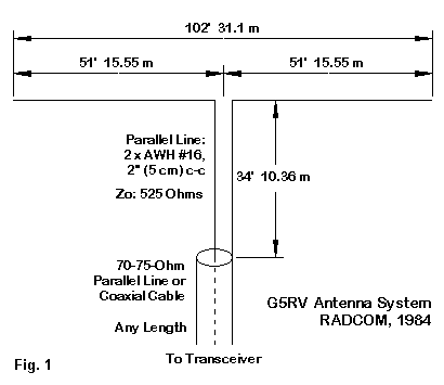
However, we conventionally sketch the G5RV antenna system as in Fig. 1. The center-fed doublet has a section of parallel transmission line extending from the radiating wire feedpoint to a junction with the "main" feedline. Curiously, Varney specifies the length of the matching section as 34.0' or 10.36 m. Using the same constant for a half-wavelength (492), the section is a half wavelength at 14.47 MHz. The prescribed length assumed a velocity factor (VF) in the line section of 0.98--hence the final length. Many folks presume that the original impedance of the matching section line used in the G5RV is 450 Ohms. However, Varney specifies home-made open wire feeder composed of AWG #16 copper wire spaced 2" (5 cm) apart. The characteristic impedance of such line by standard calculations is closer to 525 Ohms. At 14.15 MHz, the line is 1/2-wavelength long, thus replicating the feedpoint impedance. Hence, the line Zo is--at 20 meters--of little consequence. A 3/2-wavelength wire--if properly cut--should present a feedpoint impedance slightly higher than a 1/2-wavelength resonant dipole: about 90 Ohms. Hence, the impedance at 14.15 MHz at the base of the matching section should also be about 90 Ohms. Thus did Varney design the G5RV antenna system for a 75-Ohm "twinlead" or coaxial feeder. There seemed to be an instant misunderstanding of the 1/2-wavelength line used by Varney in his antenna system, since recommendations immediately began to appear for the use of twinleads other than the home-made open-wire feeder used in the original. At 14.15 MHz, 300-Ohm solid ribbon twinlead with a VF of 0.82 (using numbers from the RADCOM article) requires 28.5' or 8.69 m of line for the matching section. However, the recommended length is 28' or 8.5 m. This latter value is closer to but not identical with applying the ribbon VF value to Varney's 34' length--which already has a VF of 0.98 built into its length. Likewise 300-Ohm ribbon with windows has a VF (in the article) of 0.90. Calculating its length using the 492 constant yields 31.29' or 9.54 m. However, the recommended length of such line is 30.6' or 9.3 m, the values one would arrive at by applying the 0.90 VF value to Varney's 34' length. With so much confusion built into the basic accounts of the G5RV, there can be little wonder that the antenna has become the subject of endless variations, some being serious attempts to arrive at an ideal antenna of its type, others being generated simply to sell commercial versions of the antenna. We have not yet tried to place the antenna on bands other than 20 meters. It is in pursuit of this goal that the G5RV has been taken well past its original intent. Remember that, even though Varney thought the G5RV would provide a good match on 20 meters for a 75-Ohm main feedline, he believed in using an ATU at the rig end of the line. Some Small Facts About Wire AntennasBefore we take the plunge into other bands, we should pause to review the methods by which the G5RV antenna system emerged and how well they play in the 21st century. The review will not be simple, because many of the notes are partially accounted for by the developer of the system. However, those same notes may be at odds with common but erroneous interpretations of the antenna. This feature will hold true without ever leaving 20 meters or straying very far from the design frequency, 14.15 MHz. The equation for calculating the length of an antenna consisting of multiple half-wavelengths has a long and honored history when well used. In fact, it is very well used when calculating non-resonant antennas or antennas for which resonance is not at all crucial. Where we require some degree of precision in determining the length of a resonant antenna, the equation turns out to be quite off the mark. Since Louis Varney stated that he intended to use the antenna system with an antenna tuner, he effectively implied that the equation used to determine the 102' length was sufficiently accurate for that method of operation. As well, his estimate of the feedpoint impedance, repeated at the end of the 34' matching section of parallel transmission line, was also within the limits of accuracy necessary for using the system with an ATU. However, 102' is not a resonant length of wire at 14.15 MHz, and its resistive impedance component is not 90 Ohms. These latter facts, which we shall embellish shortly, would be not problem if the general conception of the G5RV antenna system included the use of an antenna tuner. However, the antenna has acquired a reputation for being able to provide under 2:1 SWR on more than one band--without qualifications needed to confine the claim to a reasonably clear arena of truth. So the following notes are more applicable to understanding why the general conception--rather than Varney's--is off base. We should note two facts about wire antennas. First, in the HF region, we have tended to blithely ignore the fact that changes of wire diameter have an effect upon the resonant length of a wire antenna and upon the feedpoint impedance. We tend to use "cutting" formulas as if they were wholly unrestricted in scope and always accurate, regardless of the wire we select. For HF wire antennas in the U.S., we tend to use wires as small as AWG #18 (0.0403" diameter)--such as copperweld--and as large as AWG #12 (0.0808" diameter) hard drawn copper, not to mention the common sizes in between. The wire diameter is small compared to a wavelength (about 834.5" at 14.15 MHz); nevertheless, a 2:1 change of wire diameter will have a recordable affect on the wire's resonant length and feedpoint impedance. Second, as we move a horizontal wire antenna to varying heights below about 1 wavelength, we shall find a second source of variation in the resonant length and feedpoint impedance of a wire antenna. Unlike variations due to wire diameter, which are quite regular, the variations due to height tend to follow cyclical patterns that repeat every half-wavelength. We can sample some of these variations from the tables that follow. In each case, I modeled 102' copper wires from AWG #18 through AWG #12, using NEC-4, which is more than adequate to provide accurate data. The models used 101 segments with a source centered on the wire. The test models were initially modeled in free space and then at two different heights above average ground (conductivity: 0.005 s/m; permittivity: 13). The upper height was 65.62' or 20 m, close to 1 wavelength above ground. The lower height was 32.81' or 10 m above ground. Let's see what the models report. Source Impedance of a 102' Wire at 14.15 MHz
Free Space
Wire Dia. Feedpoint Impedance 75-Ohm
AWG R +/- j X Ohms SWR
#12 102 - j 48 1.869
#14 103 - j 51 1.914
#16 104 - j 53 1.958
#18 105 - j 55 1.999
65.62'/20m
Wire Dia. Feedpoint Impedance 75-Ohm
AWG R +/- j X Ohms SWR
#12 104 - j 49 1.883
#14 104 - j 51 1.928
#16 105 - j 54 1.972
#18 106 - j 56 2.012
32.81'/10m
Wire Dia. Feedpoint Impedance 75-Ohm
AWG R +/- j X Ohms SWR
#12 111 - j 56 2.048
#14 112 - j 59 2.093
#16 112 - j 61 2.136
#18 113 - j 63 2.177
The SWR numbers are overly precise relative to the rounded impedance values. The intent is to show clearly the general trends. The thinner the copper wire, the higher the resistive component of the impedance, despite the fact that the wire is ever shorter of resonance. As well, although the impedance values at a 1-wavelength antenna height are very close to the free-space values, the impedance figures at a 1/2-wavelength height show some departure from the free-space values. Finally, the wire is well short of resonance at the design frequency. Otherwise put, for precision of resonant length, the traditional equation simply will not do. I replicated the exercise when I added in a 34' or 10.36-m length of 525-Ohm feedline with a velocity factor of 0.98. This provides an electrical half-wavelength of line, that is, the equivalent of 34.77' or 10.60 m at 14.15 MHz. Remember that the intent of this line section on the design frequency is to replicate the wire feedpoint impedance at the end of the so-called matching section. For this exercise, it is unnecessary to model the parallel transmission line with physical wires. One may use the TL facility within NEC-4 software to provide a non-radiating mathematical model of a perfect (lossless) transmission line. Since Varney's writings anticipate that the antenna builder will respect the requirement of parallel transmission line to sustain its balance, the non-radiating aspect of the NEC TL facility is within the bounds of the exercise. Because the line is relatively short, the difference between a lossless line and a real line constructed according to Varney's specifications will almost too small to notice. On the other hand, because we are using a physical length that is only close to but not exactly a half-wavelength at the design frequency, we should expect to see small variations in the resulting impedance and SWR values. The following table records the results of this exercise. Source Impedance of a 102' Wire and 34' Line at 14.15 MHz
Free Space
Wire Dia. Feedpoint Impedance 75-Ohm
AWG R +/- j X Ohms SWR
#12 102 - j 52 1.933
#14 103 - j 54 1.979
#16 104 - j 57 2.024
#18 105 - j 59 2.066
65.62'/20m
Wire Dia. Feedpoint Impedance 75-Ohm
AWG R +/- j X Ohms SWR
#12 104 - j 52 1.946
#14 104 - j 55 1.993
#16 105 - j 57 2.037
#18 106 - j 59 2.079
32.81'/10m
Wire Dia. Feedpoint Impedance 75-Ohm
AWG R +/- j X Ohms SWR
#12 111 - j 60 2.111
#14 111 - j 62 2.158
#16 112 - j 64 2.203
#18 113 - j 66 2.245
There are only slight differences between the two tables, and the bulk of those differences result from the fact of choosing a physical approximation of a 1/2-wavelength line rather than using an exact 1/2-wavelength line. However, it is likely that the modeled line is closer to 1/2 wavelength than will be most lines cut for a physical implementation of the G5RV antenna system. At the design frequency, we need not explore the consequences of using something other than the line specified for the antenna. The use of 300-, 400-, and 450-Ohm lines--if each is an electrical half-wavelength--will result in virtually identical tables for 14.15 MHz. A more important question concerns the antenna length. As initially specified, the wire is too short to be resonant at 14.15 MHz. But what length might seem more resonant? The spread of impedance figures suggests that we might use a compromise between the resonance at a 20-m height and resonance at a 10-m height. In fact, I used this compromise to arrive at a length of 103.35' or 31.5 m. The compromise does not represent an ideal situation, only a convenient one. The change of impedance and resonant length does not follow a simple progression with decreases in height. Instead, the values change cyclically in half-wavelength increments (ignoring height below about 0.2 wavelengths above ground). The sample heights used here do not necessarily represent the extremes that might appear at other heights. With these qualifications, we can examine the data reported by NEC-4 for the revise wire length with the 34' line attached. Since the free-space values and the 20-m height values are so similar, I have omitted the free-space portion of the exercise. Source Impedance of a 103.35' Wire and 34' Line at 14.15 MHz
65.62'/20m
Wire Dia. Feedpoint Impedance 75-Ohm
AWG R +/- j X Ohms SWR
#12 111 + j 7 1.494
#14 112 + j 7 1.497
#16 112 + j 6 1.504
#18 113 + j 6 1.515
32.81'/10m
Wire Dia. Feedpoint Impedance 75-Ohm
AWG R +/- j X Ohms SWR
#12 119 - j 1 1.586
#14 119 - j 2 1.592
#16 120 - j 2 1.601
#18 120 - j 3 1.613
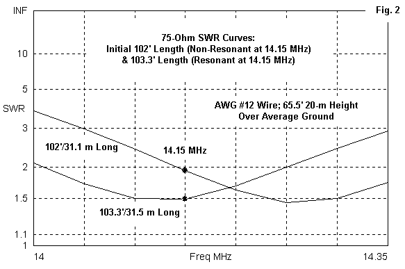
Increasing the length of the wire toward resonance, of course, increases the resistive component of the source impedance. Hence, there is a limit as to how low the 75-Ohm SWR can go by this strategy. As well, as the wire thins, the resistive component goes up. We seem to have gained a usable 75-Ohm SWR at the design frequency, but obviously the 50-Ohm SWR would be well above 2:1. In the days before fixed-tuned output circuits in transmitters, the old pi-network amplifier output circuits--with variable "tune" and "load" controls--would have easily provided a match to these impedance values in 20 meters. As well, they fall well within the range of almost any ATU, even the limited range versions incorporated into some modern transceivers. However, an SWR value at a spot frequency does not tell the entire story about antenna performance. We are as interested in the SWR bandwidth as we are in the particular value at some given frequency. So I ran frequency sweeps of the two versions of the G5RV antenna, both with the 34' line attached.
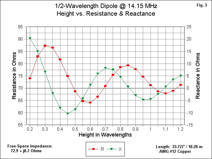
Fig. 2 shows the curves for the short and the long antennas. Clearly, the longer length favors the lower end of 20 meters, while the 102' length favors the upper end of the band. The impedance level of a G5RV is high enough that we cannot obtain full band coverage from the wire and line combinations. In addition, the 1/2-wavelength line section is 1/2 wavelength only at the design frequency. Hence, it contributes to a narrowing of the SWR bandwidth. We may note in passing that a common resonant 1/2-wavelength dipole of any of the wire sizes sampled in this exercise would easily cover the 20-meter band with under 2:1 SWR. Moreover, an ATU would free us from concern about the 2:1 SWR that marks the limit of full output from most modern transceiver designs. Nonetheless, it is interesting to note that the 3/2-wavelength wire tends to show a narrower SWR bandwidth than the shorter half-wavelength dipole. The narrower operating bandwidth will, of course, be a matter of concern for anyone who tries to use a G5RV antenna system without an intervening ATU. Unfortunately, this latter mode of operation seems to be the rule rather than the exception--at least until one experiences first hand the limitations of the system. A Side-Note on Height vs. Feedpoint ImpedanceI have noted that for any single-wire doublet, the source impedance varies with the height above ground. The variation is most significant in the region below a 1-wavelength height. The differences in the G5RV feedpoint impedance reflected this variation, but perhaps not as convincingly as it ought to do. Let's begin with a common center-fed dipole at 14.15 MHz. We shall make it from AWG #12 copper wire. Our model will be resonant in free-space. A length of 33.727' or 10.28 m satisfies this requirement within +/-j 1 Ohm reactance. The wire's impedance in free space is 72.9 + j 0.7 Ohms. I then set the antenna over real average ground, beginning at 0.2 wavelength and continuing in 0.05-wavelength increments to 1.2 wavelengths. The effects of the height changes on the feedpoint resistance and reactance appear in Fig. 3.
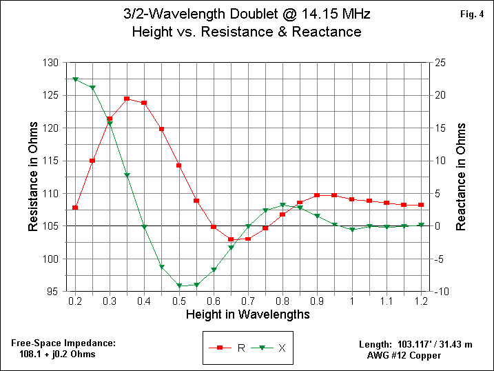
As noted earlier, the resistance and reactance cycles peak at 0.5-wavelength intervals of height. However, the resistance and reactance curves are not synchronized. The reactance peaks occur about 0.15-wavelength higher than their closest resistance peaks. The reactance swings allow us to re-interpret the data in this way: The resonant length of a 1/2-wavelength dipole changes with height, especially within the range of heights shown in Fig. 3. But, even if we resonate the dipole at each height, the feedpoint impedance will still show cyclical changes as we increase the height throughout the range that we have sampled. A 3/2-wavelength doublet exhibits the same sort of impedance swing. Let's construct a 14.15-MHz resonant 3/2-wavelength doublet from the same AWG #12 copper wire. If we resonate it in free space, it will be 103.117' or 31.43-m long. Its free-space feedpoint impedance will be 108.1 + j 0.2 Ohms. Now we are ready to perform the same set of exercises that we performed on the dipole.
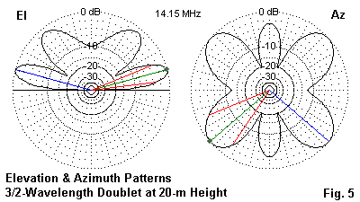
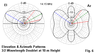
Fig. 4 shows the results of our test runs. Once more, the resistance and reactance vary considerably as we change heights. The reactance reaches its peaks about 0.15-wavelength higher than height at which the resistance values peak. Perhaps the most notable differences between the dipole and doublet graphs are two: First, the doublet peaks and dipole peaks do not occur at the same heights above ground, although the impedance components for both antennas show 1/2-wavelength cycles. Second, the feedpoint impedance of the longer doublet smooths out rapidly above 1 wavelength, while the 1/2-wavelength dipole impedance components continue to show noticeable cycles. Not only does the impedance show differences with height, but so too do the elevation and azimuth patterns. Here, we may illustrate by taking the elevation and azimuth patterns of the 3/2-wavelength doublet at 20-m and at 10-m heights above ground.
The elevation pattern in Fig. 5 shows the typical double lobe structure of any horizontal antenna just below 1-wavelength above ground. The azimuth pattern presumes that the antenna wire is stretched horizontally across the graphic and is taken at the antenna's take-off (TO) angle (the elevation angle of maximum radiation), namely, 14 degrees. It shows 6 lobes, just as we would expect of any wire antenna half-way between 1- and 2-wavelengths long. Note the distinctness of the angular lobes; that is, note the depth of the null off the ends of the antenna.
Fig. 6 shows the equivalent patterns when the antenna is half the height of the first model. At just below a half-wavelength in height, we have only a single elevation lobe, just as would any horizontal single-wire antenna at the same height. The azimuth pattern uses a TO angle of 28 degrees and is clearly kin to the one taken at 20 m above ground. However, note the shallower null off the ends of the antenna wire. Radiation off the ends of the wire is down only about 4 dB compared to radiation at the maximum gain angles, compared to a 12-dB differential for the higher version of the antenna. Like any other wire antenna, the 3/2-wavelength doublet--the heart of the G5RV antenna system at 20 meters--requires reasonable careful orientation if the user has in mind any particular target areas for communications. Likewise, height will always benefit a single-wire antenna, at least to the point where the vertical beamwidth matches as best possible the typical variations in the skip angles on 20 meters. ConclusionWe have reviewed some of the design elements that went into the G5RV antenna system at its design frequency of 14.15 MHz, including some apparent confusions surrounding alternative "matching section" lengths when using different parallel transmission lines. As well, we have shown some of the limitations within the simplified design procedure used to develop the basic G5RV length. Perhaps of equal or greater significance has been our foray into understanding some of the factors that influence the operation of wire doublets that are usually absent from simplified cutting formulas. Every change that we make from a design that we use as a starting point has consequences for how well the antenna performs compared to the original. The importance of these changes can range from negligible to monumental, depending upon our operating circumstances and our expectations. Louis Varney expected to use his G5RV antenna system with an ATU on many bands without much regard for where on each band his strongest lobes were pointed. Consequently, the antenna worked very well for him. However, much of the indirect reputation of the G5RV has to do with operating on at least some bands without an ATU. As well, expectations of lobe direction have largely been silent, leaving each user to bring his or her own expectations to the table. As a result, many users have been overjoyed, while many other have been disappointed. Since we have extracted about as much useful data as we can for the basic design frequency--the 20-meter band--we may next turn to trying to use the G5RV on other bands.
|

