|
What would I choose? Let me be a bit more specific. Suppose I wanted to work 40 through 10 meters. And further suppose that I want to know where my signal is going. Now what would I choose. The 40-Meter Dipole Starting Point The most common answer to the problem I just posed is a 40-meter #12/#14 copper wire dipole, fed with parallel transmission line for use as a multi-band doublet. Fig. 1 tells the simple construction tale.
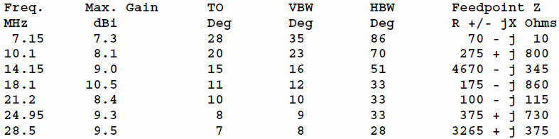
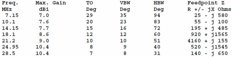
Placed high enough in the air, the 67' doublet performs very well. Its bi-directional pattern on 40 has good side QRM rejection, and with enough altitude, the elevation angle makes DX a real potential with every band opening. Let's place the antenna at a height of 66' up and see what the models tell us that we can expect by way of performance.
The TO angle is the elevation angle of maximum radiation. I have also provided information on the vertical and horizontal beamwidths (measured to the -3 dB points from the maximum strength bearing). We often neglect this information, but the data tell us some important facts. The vertical beam width is a rough measure of the range of elevation angles that we can count on for good communications. The horizontal beam width tells us how broad or narrow our signal is and hence how careful we must be in aiming the antenna--either when we build it or when we rotate it. One of the amusing facets of reading lots of e-mail is discovering how many beam users demand 1-degree aiming accuracy when their beam widths are well over 50 degrees. The 67' doublet shows the anticipated lowering of the TO angle as we increase frequency. As we increase the frequency, the antenna is increasing in electrical height, that is, its height as a fraction of a wavelength. So we expect the beam angle to be lower on the upper bands. The beam widths--both vertical and horizontal--narrow with rising frequency. Still, the vertical beam width is wide enough on all bands to catch the main stream of long-range skip. And the horizontal beam width is sufficiently broad to make aiming non-critical - but not unimportant. The range of impedances at the antenna suggests that with a parallel transmission line and an ATU, we should be able to effect a match on all bands. 20 and 10 meters might present slight problems, but changing the line length will likely solve them by presenting the ATU with impedance values it can handle. However, the gain column presents us with a small problem. The maximum gain of the 67' doublet occurs on 17-meters, takes a large dip above that band, and then slowly rises once more. For a simple wire, the actual gain numbers are not the problem. The question we want to ask is this: why does the dip occur? Fig. 2 can help us figure out what has
occurred.
The azimuth patterns overlaid on the plot are for 40, 15, and 10 meters. The 40-meter pattern is the typical oval. As we increase frequency, the oval grows narrower (decreasing horizontal beam width) while the gain increases--up to 17 meters. On this band, the 67' doublet is about 1.25 wl long: an extended double Zepp (EDZ). We expect about 3 dB gain over a dipole from an EDZ, and if we compare the 40-meter and 17-meter gain figures, we can see that we get it. Above 17 meters, the antenna is longer than 1.25 wl. At 15 meters, the antenna is about 1.5 wl long. The main lobe is no longer broadside to the antenna, but, as shown in Fig. 2, it is broken into 6 distinct lobes. The lobes broadside to the wire are no longer the strongest. As we move into the 10-meter region, where the antenna is 2 wl long, we have a pattern composed of 4 lobes at roughly 40-degree angles to the wire. For those unfamiliar with pattern development as an antenna becomes multiple wavelengths long, the following rules of thumb apply. For an antenna that is N wavelengths long, where N is an integer (like, 1, 2, 3), the number of lobes is twice the value of N. So a 2 wl antenna has 4 lobes, and a 1 wl antenna has only 2. For antenna lengths that are N.5 (like 1.5, 2.5, etc.), the number of lobes will be the sum of the number of lobes we get at N and at N+1. At 15 meters, where the antenna is 1.5 wl long, 1 wl gives us 2 lobes and 2 wl gives us 4 lobes, for a total of 6. The higher number at N.5 wl values arises because the new lobes are growing and the old ones shrinking--and they are nearly equal strength at the N.5 wl points. The 44' Wire Solution The problem with wire lengths over 1.25 wl is that we are no longer sure that we have a good signal broadside to our antenna. Suppose I put up a wire in Tennessee, running it NW to SE. That makes it broadside to Europe in one direction and to VK/ZL-land in the other. Not a bad set up. However, the main lobes for frequencies from 21 MHz up are no longer going where I want them to go. Where they go may result in interesting contacts, but we set up our problem at the beginning so that it includes the need to keep our signals where we want them. There is a simple solution to this problem, but it may not be the one some folks would expect. Conventional wisdom tells us always to make antennas bigger and longer. However, the solution to our problem is to make our doublet shorter. Let's try a doublet that is 44' long, as in Fig. 3. Again, #14 or #12 AWG copper wire will do just fine for the antenna.
The first question we may now ask is whether we
lose anything with the shorter wire. Let's find part of the answer
in another table, modeled with the copper wire (#14 AWG) antenna 66'
above average ground.
The gain figures begin about a quarter dB below the figures for the 67' doublet on 40 meters and climb steadily. The elevation angles of maximum radiation and the vertical beam widths are virtually identical to those for the longer doublet. The shorter antenna provides a broader horizontal beam width on every band, which makes aiming less critical. The pattern of impedances offered at the feedpoint differs in detail from that of the longer doublet, but the values are manageable. To see one of the major advantages of our short
doublet, we should look at Fig. 4.
The composite azimuth patterns for the doublet on all of the bands for which it is intended have their major lobes exactly broadside to the wire. The 44' length was no accident. On 10 meters, this length is about 1.25 wl long, the standard EDZ length. The 10-meter pattern shows the anticipated strong main lobes plus the emerging "ears," secondary lobes that will become the major lobes at higher frequencies. On 15 meters, the antenna is about 1 wl long, and on 30 meters it is just under the right length for a half wl dipole, which is indicated by the low resistive impedance and the capacitive reactance for 10.1 MHz. On 40 meters, the antenna is between 1/3 and 3/8 wl long, about the minimum length we should use. Anything shorter would show very low resistance values and very high reactance values--a difficult situation for any ATU to handle. If I wanted to aim at both Europe and at Australia and New Zealand on all bands from 40 through 10 meters, then the 44' doublet is the superior antenna to the longer 67' doublet. Of course, larger (102' or 135') all-band doublets break into fragmented lobe patterns at lower frequencies than the 40-meter dipole with which we started. So, if we make aiming one of the criteria for our antenna, the 44' doublet may be the way to go. Two side notes. First, if we want to cover the bands only up through 20 meters, but want to include 80 and 75 meters within the frequencies for which we are well-aimed, then an 88' doublet would meet our needs. Of course, there is nothing magic in the precise length numbers chosen, since a length change of a foot or two will change almost nothing in terms of performance. The bands with the highest reactances at the feedpoint might show the greatest change in value as we alter the antenna length, but the feedpoint values on the other bands would hardly change enough for an ATU to notice. Second, height is a major consideration with this sort of antenna. Perhaps 66' is not feasible for everyone. However, every foot of (safe) height that you can add to the antenna, the better it will work. This principle goes back to the days of George Grammer of ARRL, who preferred to add height rather than elements to his antennas. The idea is no less true today, although there are some limits. Once we get above 1 wl, there may be some holes in our DX elevation angle coverage at certain antenna heights. In Grammer's day, only on 10 meters and VHF did most hams think about heights above 1 wl or so. If you decide to construct a single-element antenna, the 44' doublet has some interesting properties that provide advantages over other types of multi-band doublets. It is an antenna worth considering--if you can have only one wire.
|