|
Small Magnetic Loops
History in Photos
Larry Nelson - K5IJB
|
|
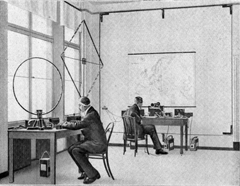
Germany - Rund Funk Radio - circa 1920s
Two small loops mounted on tables and large
loop mounted on far wall with feedpoint
shown at lower left. |
|
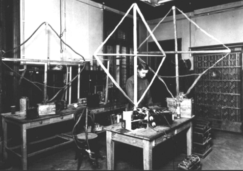
Three small loops shown in the Paris test
laboratory of FM inventor Major E. H.
Armstrong. Circa 1920s. |
|
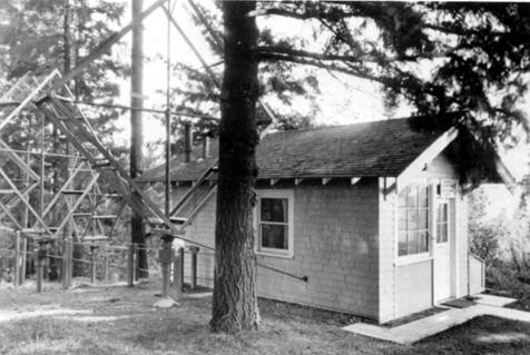
Control point for VLF receivers at Council Crest
near Portland, Oregon. Photo taken
1927 when this coast station was owned by
Federal Telegraph Company. Note
the very large outdoor receiving loops. |
|
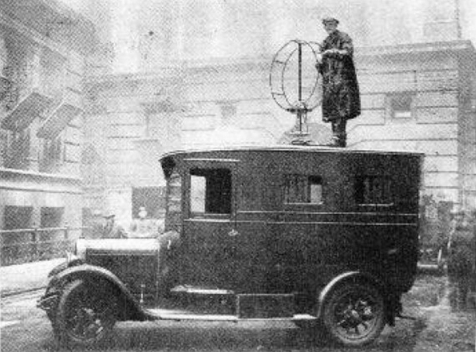
Radio direction finding truck
used by British Post Office
in 1927 to find illegal radio transmissions. |
|
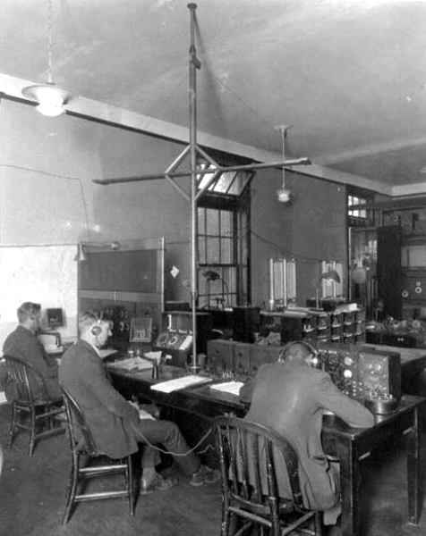
Operating room for coast station WCC
Cape Cod, MA
showing large indoor receiving loop. Circa 1930s. |
|
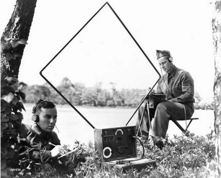
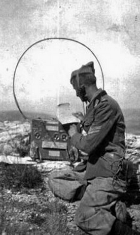
SCR-131 field radio used during
1930. Frequency range was 4.0-4.36 MHz with the LP-7 loop
antenna used for both transmitting and receiving. |
|
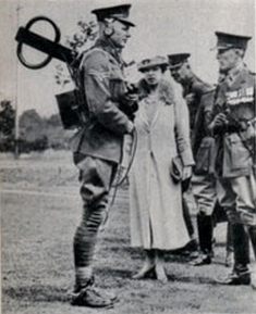
British solder demonstrates a small loop antenna to the Queen in 1937. |
|
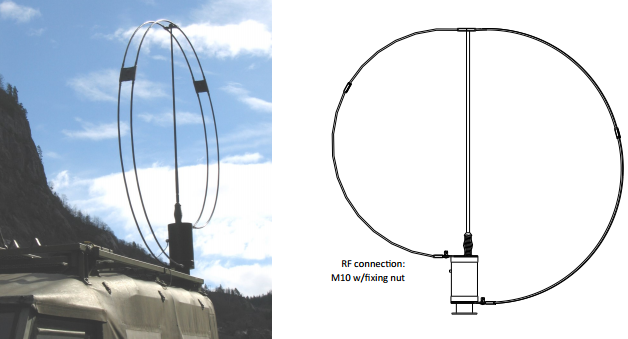
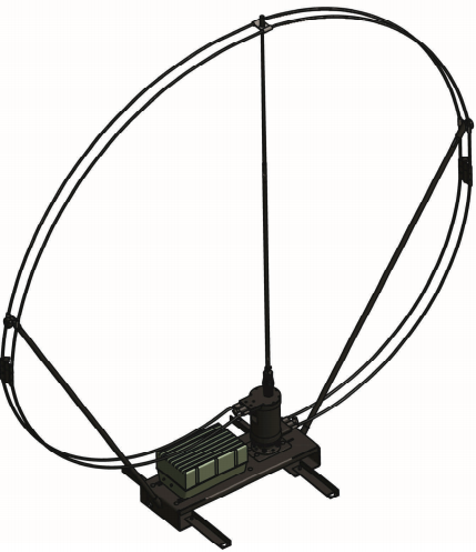
COMROD (2004). The
HF230-B is a compact HF antenna for rapid deployment
to create a base station
working the frequency range 1.6-30 MHz and designed to provide Near Vertical
Incident Skywave (NVIS) |
| |
|
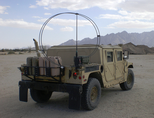
COMROD (2005).
HF230L_OTM is a compact HF antenna for on-the-move
vehicular platforms from 2 to 30 MHz. It is designed to
provide superior Near Vertical Incident Skywave (NVIS)
performance at distances from 0 to 500 km allowing
continuous communications for ground-wave, NVIS and skywave applications. |
| |
| |
|
|
|

|
| |
| |
| |
|
|