|
Magnetic loops can take on a variety of shapes - circular, octagonal and hexagonal. The most efficient shape is circular because it has the largest area or maximum capture area for signal. In each of the coupling methods below, the capacitors connected across the ends of the loop are used to resonate or tune the antenna. The other capacitor matches the low impedance of the loop to the transceiver. There is some interaction with the resonating capacitors so that tuning and matching is an alternating adjustment process in order to minimize SWR and maximize loop current. The U.S. Army Loop antenna was designed by Kenneth H Patterson working for Department of the Army, US Army Limited War Laboratory, Aberdeen Proving Ground, Maryland. Patterson first described this configuration in Electronics magazine, August 21 1967. The loop configuration was developed for South East Asia to boost MF and HF signals covering 2-5MHz range when working out of narrow valleys and heavy forests. It was designed primarily for compactness being just 12 feet wide, portability, and quick assembling and dismantling for packing into small spaces. The simplified image below shows the basic design of the U.S. Army Loop antenna. An octagonal loop antenna was constructed with 5 ft sides made from 1.75 inch diameter aluminium tube with gold plated ends. Gold plating ensured that overall losses were less than 0.1 ohms and the loop’s efficiency was high and comparable to a full-size dipole.
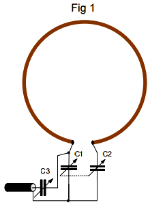
Basic tuning and matching circuitry employs two high voltage twin gang 468pF variable air-spaced capacitors. An extra 450pF was switched across C1a and C1b to cover the entire 2-5MHz frequency range for coarse tuning. For improved fine tuning, capacitors C2a and C2b were provided with a 12-way switch to select one of twelve high grade mica capacitors (750-8250 pF) for additional impedance matching. Figure 1: Capacitors C1 and C2 resonate the loop and equally share the high voltage produced as a result of the loop’s high Q, but at the expense of reducing the effective tuning capacitance by a 1/2. C3 provides the matching of the loop’s low impedance to the transceiver’s 50Ω. This is easiest to implement using two twin gang variable capacitors. The two sections of a single gang capacitor wired as a split stator for C1 and C2 and C3 formed similarly.
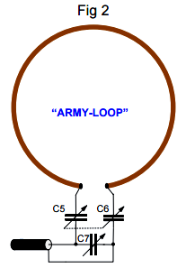
Figure 2: Capacitors C5-C6-C7 act as a voltage divider. This arrangement increases the voltage rating of the combined tuning capacitors, but reduces the effective tuning capacitance by 1/3. Capacitor C7 matches the loop to the transceiver. C7 must not be ganged with C5 and C6.
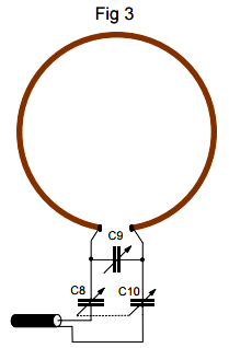
Figure 3: A single capacitor C9 is used to tune the loop, but must be able to withstand the loop’s very high voltages. Each of the ganged coupling capacitors C8 and C10, which are connected in series with the coax, share half the loop's high voltage.
Even though the four diagrams above show single variable capacitors, high power loops often use two series variable capacitors to double the voltage rating and avoid flashover between the capacitor plates. Even at modest QRP power levels voltages in excess of 1000 volts can be present across the tuning capacitor and matching capacitor. |