|
As with all ham stations QRO or QRP, ten percent of a station’s success in quality QSOs is the equipment and the operator. Ninety percent is the antenna. This is especially true in QRP since with very low power, by comparison to the Power Mongers, we need to get more ERP per watt out into the ether to be heard. So when I got back into QRP a few years ago I found the fascinating world of antennas and RF radiators to be an exciting challenge and a means to find the perfect antenna which I call the New Carolina Windom.I don’t have room for an 80-meter dipole or long wire so I have to restrict the length to 100 feet or less. Besides, my primary interests are working only CW on 40, 30, 20, and 15 meters. Based upon these parameters, I have found what I consider to be the perfect antenna. The antenna I will show you how to build in this article evolved from a concept that had its beginning back in 1929 when Loren G. Windom described his invention in the September issue of QST, 1929, pages 19-22.A few years ago, three hams, Jim Wilkie (WY4R), Edgar Lambert (WA4LVB), and Joe Wright (W4UEB), came up with an idea for an off-center fed dipole that carried Windom’s single feed line antenna to the next level. It has since become known as the Carolina Windom. This is called the traditional Carolina Windom since it was the first attempt at creating this specific type of multi-band antenna based loosely on Windom’s original concept.The difference between the new Carolina Windom and the original Windom antenna is that the original Windom is not a dipole.
New Carolina Windom
shown cut for 40, 20, 15 and 10
meters. The other interesting feature is that the 10 feet of coax from the balun is terminated in a choke or line isolator. I have fitted the 10 foot stub with PL-259 UHF connectors on each end. This allows the coax vertical radiator to be easily removed if desired. It is designed to hang vertically which is one reason why this antenna is so effective. The radiation pattern when using the vertical radiator combines both horizontal and vertical radiation components and lowers the effective angle of radiation getting more of your signal near the horizon.This antenna is in use the world over by DX'ers and DX'peditions. In one Navassa DX'pedition, of the 33,000 QSOs made, more than 27,000 were accomplished with this antenna. The DX'pedition team also had a beam and verticals, but the New Carolina Windom was the antenna they used. Its reputation for excellent performance is so good that it served as one of the antennas in setting two 40 meter "mile-per-watt" world records of nearly 4,000,000 miles-per watt.The antenna can be used without the vertical radiator but the radiation pattern will lose the low angle component and may make the antenna less effective. If the vertical radiator is removed then you should move the line isolator to the bottom of the balun .
Here is the math for designing the New Carolina Windom cut for your lowest band operation:
Using 7.1 mhz as lowest frequency of operation:
The new Windom can be designed for 160, 80/75, or any fundamental frequency you desire as the lowest band of operation. It should perform better on that fundamental frequency and still resonates on the harmonically related bands without a tuner. Keep the original ratios (33% and 67%) the same by using the formula. You will have to adjust the balun to choke length of RG58 in the same ratio by doubling the length from 10 feet at 40 meters to 20 feet at 80 meters and 40 feet at 160 meters. The ratio is meters / 4 = length of vertical feeder.
Brief History of OCFD Antenna
Development
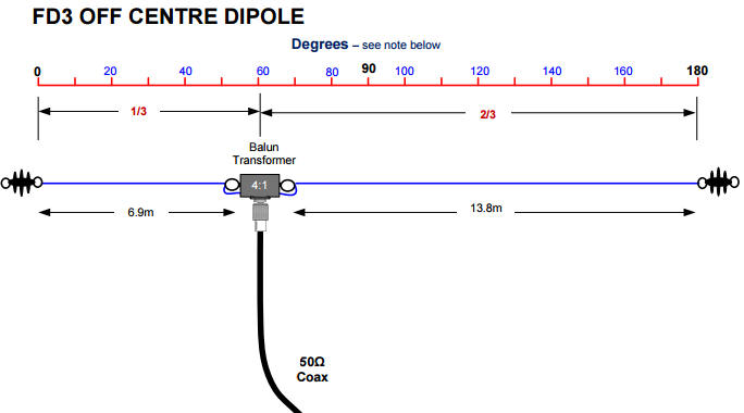
During the mid 1920's Associate Professor Bill Everett and his student John Byrne conducted research on dipoles being fed by single wire transmission lines. Everett’s university friend L Windom (W9GZ), who often helped in the experiments, published the experimental results in the September 1929 issue of QST and clearly stated he was reporting on the work of others. The following month Everett’s research was finally published in the Proceedings of the IRE with Associate Professor Everett and Byrne listed as authors. In 1930 the Wireless Institute of Australia published an article based on Windom’s QST article and the name "Windom" became associated with the antenna. Then in 1937 J Macintosh VS1AA (GM3IAA) suggested that Windom’s single wire feed be re-positioned 1/3 off-centre to enable multi-band operation. At that time the amateur bands were all harmonically related. Shortly after World War II, the Radio Society of Great Britain published an article, "Why Not a Windom?" and the name stuck. Interest in Europe was aroused when in 1971, Dr. Fritz Spillner, DJ2KY modified the VS1AA antenna design by replacing the single feed wire with balun and a coax feeder. This became known as the Fritzel FD4 (80, 40,20,10m) but is more correctly described as the Off Center Fed Dipole (OCFD). The half-size version of the FD4 is known as the FD3 (40,20,10m) and is the subject of this article.
Although the new WARC bands are not
harmonically related to the traditional bands, the FD4 & FD3 can
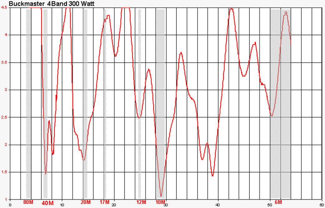
operate on the 30m,17m and 12m with additional antenna matching. Buckmaster 4-Band OCF Dipole
Our 4-Band antennas cover 40, 20, 10, and 6 meters, with no tuner required. 12 meters may also work on the 4-Band 300 watt model. The 4-Band antennas are OCF (off-center-fed), with a 23 foot leg and a 45 foot leg, totaling 68 feet - not 66 feet. See multiband OCF manual.
|

.gif)