|
Coupling Loop Configurations
for Small Magnetic Loop
Antennas
Frank
Doerenberg - N4SPP
Two main types of inductive coupling are the unshielded coupling
loop and the shielded coupling loop. No physical connection exists between the main loop and coupling loop.
The shielded loop (Faraday loop) may result in a lower SWR.

Unshielded Coupling Loop
One type of inductive coupling loop is the unshielded
loop. The conductor has to be stiff and rigid enough to retain its shape.
Commonly used are:
-
Heavy gauge
wire or small diameter copper tubing -
the conductor need not be heavier gauge than the
center-conductor of the feed-line coax.
However,heavier conductor will help retain shape of
loop, and make it self-supporting. I have used
"extra heavy" single-strand installation wire of 2.5
mm.
-
Braid of the
coax - center conductor is not used
-
Center conductor of
coax, with outer insulation and braid removed - Dielectric
material of the coax is kept and provides rigidity.

Unshielded coupling loops
(1) Solid wire (2) braid
of coax (3) center conductor of coax
The main loop and the
coupling loop form a loosely coupled transformer. Turns ratio is fixed, but
several coupling loop parameters affect the
coupling:
-
Size of the coupling loop -
standard diameter is 1/5 that of
the main loop
-
Shape of the coupling loop -
standard shape is circular. Square and octagonal also used.
-
Placement along the main loop - standard
location is
opposite tuning capacitor
-
Proximity to main loop - coupling loop
normally placed opposite tuning capacitor
-
Alignment to main loop. Plane of coupling loop coincides with that of the main loop. The coupling with the
main loop can be varied by turning the coupling loop about its vertical
axis from where the coax is connected to the point at the top of the
loop.
-
Gauge of the conductor - coils -
inductors
Shielded Coupling Loop
Another inductive coupling loop type is the shielded loop, often referred to
as Faraday Loop. The typical diameter is
1/5 that of the main loop diameter, though some
people have better results with a loop as small as 1/8 the size of the main
loop. This coupling loop configuration is typically made of a section of
coax cable for ease of construction.
There are
a number of variations:
-
coax braid or shield is
interrupted at the point half way around the loop
-
center conductor is
interrupted at that same point
-
braid and center conductor
are connected at the starting point of the loop
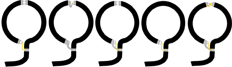
Shielded coupling loops
Variations showing braid and center conductor
connections
Some people feel
claim that the "shielding" provides better screening from "electrostatic" noise.
There is no convincing evidence that this makes any significant difference with
respect to un-shielded coupling loops. If it did make a difference, the same principle
could be applied to the main loop - which nobody does.
For the same
diameter, the unshielded and the various shielded coupling loops all have a
different self-resonance frequency. This is easily measured when not coupled to the main
loop.
Comparative Measurements
Jochen Huebl (DG1SFJ)
performed comparative measurements between unshielded
loops and shielded loops.
-
The coupling loop (diameter: 16.5 cm / 6.5") was
placed in the same plane as the main loop, opposite the tuning capacitor
-
Distance d between the two loops was varied:
(1)
starting with the
coupling loop against the main loop with some insulation between them
(2)
then moving the coupling loop closer to the center of the main loop (max 10 cm /
4 inch)
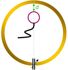
-
As induced
magnetic field decreases with distance, coupling between the loops becomes
weaker as distance is increased
-
No
difference exists as to coupling loop's placement - inside the main loop or outside the main loop
-
Conclusions
- SWR increased linearly with distance
between coupling loop and main loop
- Lowest
SWR was obtained with coupling loop closest to main loop
- Shielded coupling loop had slightly better SWR than unshielded
coupling loop
- Return-loss increases
rapidly when distance is increased to one inch, then becomes
flat
with further increase in distance
- Shielded coupling loops had about 6 dB better coupling
Source: http://www.nonstopsystems.com/radio/frank_radio_antenna_magloop.htm
Additional Reading
|