|
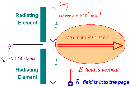
Radio communication relies on the use of a transmit antenna to send information "over the air" from a local position to another receiving antenna at some remote position. The transmit antenna produces electromagnetic energy comprised of an electrostatic field traveling with a perpendicular magnetic field at the "speed of light" in a vacuum and (very) slightly slower through an atmosphere or other medium. Isotropic (Omni-Directional) Antenna An isotropic antenna has a omni-directional antenna that transmits radio signal energy, or receives radio signal energy equally in all directions. Consequently, energy supplied to a loss-less isotropic antenna radiates equally over the surface of a sphere with an surface area related to its radius. Standard Half Wave "Dipole" Antenna Transmit and receive antennas need not be identical in design but the most common physical arrangement begins with a "dipole" configuration, developed by Heinrich Rudolf Hertz in 1886. This consists of two "quarter wavelength" conductors placed end to end with an electrical connection to the middle section.
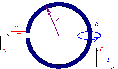
The dipole antenna has a relative gain of +2.15 dB compared to an isotropic antenna. This relative gain is not surprising as the dipole has some directivity. Electrically Short Dipole Antenna Although the half wave dipole exhibits useful power gain over an isotropic antenna, its dimensions can be cumbersome for portable devices. As we saw previously a VHF dipole designed for operation at a frequency of 150 MHz would need a total length of one meter. Small portable devices such a paging receivers would obviously be incompatible with an antenna having such dimensions. In the never ending search for miniaturized electronic devices, an equally compact antenna is essential. How can this be achieved? The simple dipole can be reduced in length so that it is no longer resonant at the operating frequency. When an "electrically short" dipole is used, it's input impedance appears capacitive and the series resistive component becomes smaller, approximately proportional to the square root of the physical length. This results in a "high Q feed impedance" requiring the reactive term to be tuned out with a corresponding inductive reactance. The energy losses associated with this resonating inductance can be significant, especially as the dipole dimensions are reduced. If the "Q" of the resonating inductor equals the "Q" of the dipole antenna then the antenna efficiency will equal one half as one half the (receive or transmit) energy will be lost in the inductor's resistive component and one half in the "radiation resistance" of the antenna. It may appear then that electrically short dipoles should perform equally as well as an isotropic antenna and almost as well as a half wave dipole (in terms of antenna gain). However, practical limitations exist when trying to match a low radiation resistance to a more standard typical value of 50 Ohms used in many RF systems. Another problem is "de-tuning". Even if this shortened antenna could be used, it would be extremely sensitive to nearby objects that could add small additional capacitive loading and shift the antenna's resonant frequency. It can be seen that an electrically shortened dipole may be feasible but not necessarily practical. Even at one tenth dimension, this VHF example dipole antenna would still be 0.1 meters total length and not fit into a small matchbox sized pager. Magnetic B Field Loop Antenna The Magnetic B Field antenna was developed to address many of the issues confronting the electrically short dipole. It is required to be physically small compared to a wavelength, have adequate radiation efficiency, provide some means to present a "reasonable" terminal impedance and be relatively insensitive to detuning effects caused by nearby objects. The simplest loop antenna consists of a wire loop with an AC current flowing in the loop. This current generates a magnetic field that is responsible for radiation, in much the same way the previous dipole antenna operated. The inductance of this loop is predictable and can be "tuned out" with a capacitor placed across a gap in the loop.
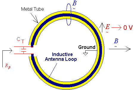
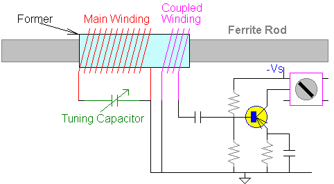
This style of antenna is often used for direction finding and has a sharp "reception null" when turned broadside to the incoming magnetic field. The "ferrite rod antenna" used in small AM broadcast radios operates much the same way and will exhibit a signal null when pointed end on to a radio station.Magnetic loop antennas also receive great interest from radio amateurs for transmission and reception at frequencies below 30 MHz and where available space required for a full dipole antenna is unavailable. I have found many excellent implementations on the web that have achieved radiation efficiencies that are comparable to a standard dipole despite useful reductions in size. Magnetic loop antennas have some interesting directional advantages. Sometimes it is advantageous to have a directional response but in some cases it may be convenient to communicate in any direction over the surface of the earth. A vertical dipole will achieve this and produce "vertically polarized" radiation that has equal power in all directions around it. However this may be cumbersome for long dipoles. For example, a ½ wave dipole required for operation in the 80 meter amateur band would need a tower that would be at least 40 meters high. A horizontal dipole is much easier to implement, but has a "blind spot" to signals arriving at its ends. A magnetic loop antenna solves this problem. It can be placed horizontally relative to the ground and produce horizontally polarized radiation in all horizontal directions. It is also claimed that "ground effects" are less problematic for magnetic loop antennas compared to dipoles. Adding An Electrostatic Shield Some accidental reception from the electrostatic component of the incoming wave may occur due to the physical area of the conductors used in the loop antenna. This reduces the depth of the reception null as some residual energy pick up remains. This unwanted pick-up can be avoided by placing an electrostatic shield around the loop antenna.
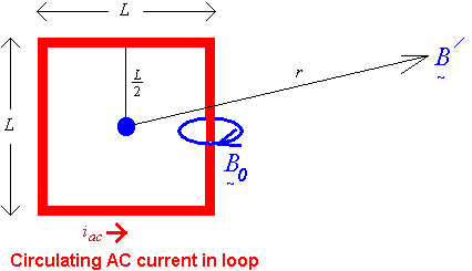
A metal tube can be used as shown. Note that a "gap" is needed to prevent the metal tube from acting like a shorted turn. The metal tube is grounded and the electrical connection is made to the magnetic loop either at its highest impedance point or over some fractional segment of its circumference. Although a balanced connection is preferred and offers greater rejection of stray electrostatic pick-up, and unbalanced connection is also feasible. Printed Circuit Board (PCB) Magnetic Loop Antennas For VHF Operation The circular loop is popular at low radio frequencies and may contain many turns of wire, resulting in a higher, more practical inductance. At higher VHF frequencies it may be desirable to "print" the antenna on a PCB as a square copper trace. "Ferrite Rod" Magnetic Loop Antenna The ferrite rod magnetic loop antenna is popular for AM radios and has also been used in some (usually older) Shortwave radios. The ferrite composition is required to exhibit low losses at the intended operating frequency and medium relative permeability . The actual efficiency is extremely low (i.e. less than 0.1 % compared to a dipole) but this deficiency is more than compensated for by its convenient small size, essential for portable radios, and the characteristic high "atmospheric noise" associated with low radio frequencies.Radiation Efficiency Predictions The overall efficiency of a magnetic loop antenna is defined as the amount of power transmitted as radio signal energy compared to the energy transmitted by a loss-less isotropic antenna. Since antennas are reciprocal, transmit efficiency and receive efficiency are exactly equal. The magnetic loop antenna could be made diminishingly small and retain 100% efficiency. However this performance requires that conductor power losses are zero in addition to any associated dielectric losses. The ohmic conductor losses are common to all magnetic loop antennas, whether they have a circular, octagonal, hexagonal, square or triangular shape. The total loop resistance is proportional to the total length and is affected by the conductor diameter (if circular) and the operating radio frequency. The most common conductor used for magnetic loop antennas is copper or silver plated copper. Impedance Matching There are three general strategies for impedance matching:
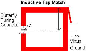
Capacitive matching The capacitive impedance matching approach relies on series to parallel impedance conversion. This impedance match is easy to implement except that all three capacitors need to have high voltage ratings. A tuning capacitor will be needed with a nominal value of 12 pF for this magnetic loop antenna and two coupling capacitors each equal to 2.9 pF will be need to transform the loop impedance down to a balanced value of 50 Ohms. A balun may be included to convert balanced to unbalanced.Inductive tap matching Since we know the effective parallel resistance of the loop, we could reason that a segment of the loop conductor would act like an "auto transformer" compared to its open end. For example, a segment equal to 1/10 the total conductor length will have 1/10 the voltage impressed over it compared to the open end and so therefore have an effective parallel resistive component. The tuning capacitor will be relatively unaffected. This method can also be used to provide an unbalanced impedance match simply by shifting the ground connection to the loop center. This also allows the tuning capacitor body (ground) to be connected to the same ground point as both will be at the same RF voltage.
Butterfly tuning capacitors are best - the main RF current does not need to pass through potentially high loss contacts. Although this central connection is at "ground" no balance is perfect. Coupled loop matching This is probably best tried by experiment. The coupling loop may benefit from an additional tuning capacitor and could be moved relative to the mail magnetic loop to optimize the final impedance match. The actual impedance ratio will probably be related to a ratio of the two areas. Summary These antennas can be purchased already made but can equally be designed and built by amateur radio enthusiasts. The offer a controlled tradeoff between size, efficiency and operating bandwidth and suit applications where space is at a premium. In this web chapter we started with an analysis of the half wave dipole antenna. This served as reference for other antenna formats. We explored the path loss equation for an isotropic to isotropic antenna (i.e. theoretically omni-directional) and defined the "aperture area" for such an antenna. We then compared the path loss for a isotropic transmitting antenna to a receiving dipole antenna and found a gain of about 2.15 dB, attributable to its directivity. The concept of "radiation resistance" was also presented, along with the concept of "skin depth" in a conductor with its associated increase in power loss at higher AC / RF frequencies. This, in comparison with an antenna's radiation resistance determines its efficiency. The radiation resistance of a half wave dipole was defined at 73.13 Ohms. The concept of reciprocity was invoked to use the isotropic antenna as a transmitting source and the dipole as a receiving directional detector. The path loss is unchanged by this swap-around. Since the magnetic loop antenna has similar directivity to a dipole, it was used in comparison to determine the radiation resistance of the magnetic loop antenna. Some associated concepts were included in this somewhat meandering derivational path. For example, the energy density S over the surface of a sphere was related to magnetic field magnitude H at a distance. The "impedance of free space" = 377 Ohms was also included in these conversions. A number of magnetic loop topologies were proposed, e.g. circular, octagonal, hexagonal, square and triangular. The directivity improvement resulting from electrostatic shielding was indicated, and a hollow tube method and a PCB method was shown. Equations were presented for antenna efficiency, impedance and tuning capacitance. Operating Q and bandwidth estimates were also provided. Some useful generalizations: The AC resistance of a loop antenna depends on the total length of the conductor, its diameter and the DC resistivity of the material and also the actual RF frequency. 2. The radiation resistance increases with loop area to a forth power and is highest for a circular geometry if the total length is constant. This need not represent a real world constraint as a square loop gave better results in one example I presented.3. Antenna efficiency is best if the radiation resistance is much grater than AC conductor loss resistance.4. The magnetic loop antenna will exhibit series inductance. The circular loop will exhibit the highest inductance.5. The magnetic loop antenna will tend to have an extremely high operating Q and therefore a narrow frequency bandwidth.Consistent with the phrase "you cannot get something for nothing" is another "you cannot get 100% antenna efficiency with minimal space and high operating bandwidth". It seems that engineering a magnetic loop antenna is the art of compromise. Three methods were shown that could be used to match the loop impedance to a standard 50 ohm resistive value
Ian Scott
|
