|
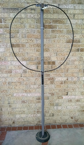
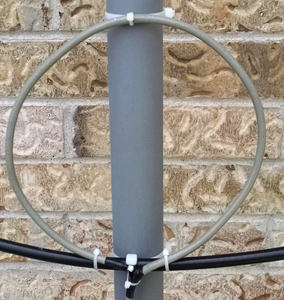
The basic configuration of an inductive-fed small magnetic loop consists of the main loop, coupling loop, and capacitor - fixed or variable. The secondary or coupling loop classifies this loop as inductive-fed. Many configurations exist for constructing the main and secondary loops. The main loop can be configured as an octagon, circle, or square. The secondary loop feeds the antenna and is referred to as the coupling loop or Faraday Loop. The Faraday Loop is commonly installed within the main loop opposite the capacitor and formed into a circle. Basic diagram of a small magnetic loop is shown below at the left. The picture at the right shows my configuration mounted on a 7-foot PVC mast (1.5-foot diameter) which slips over a 3-foot microphone floor stand. The coupling loop is barely seen at the bottom of the main loop.
Main loop Many hams construct loops with .5 - 1.0 inch copper tubing. RG-8 (model LMR-400) coaxial cable was chosen for this project because it was easy to work with. It required no tools for bending into a circle, solid center conductor for strength, and the outer conductors consisted of braid plus extra foil shield. Not only was the braid easy to solder, but the two-layer outer conductors insured less loss due to continual conductivity. The center conductor was not used. The length of LMR-400 for the main loop is referred to as the circumference. Circumference of 10 feet was chosen for this project which permits operation on 10-20 meters. The LMR-400 coax was then formed into a circle measuring approximately 39 inches in diameter. Antenna efficiency varies greatly from 10 meters to 20 meters. Choosing a circumference length becomes a compromise between efficiency and desired band operation. Two mathematical models make the circumference easy to determine. Both models are based on (1) circumference of the main loop, (2) diameter of the main loop's conductor, and (3) frequency in MHz. What-if situations can be experimented with to determine best length for the circumference. Magnetic Loop Antenna Calculator This model is web-based and easy to use. Diameter of Conductor for LMR-400 coaxial cable is .405 inches. Length and frequency variations will change antenna efficiency shown under Results. The calculator indicates the minimum/maximum circumference length at bottom right. Antenna diameter is calculated which is helpful for forming the conductor into a circle. This model calculates data for only the octagon configuration.
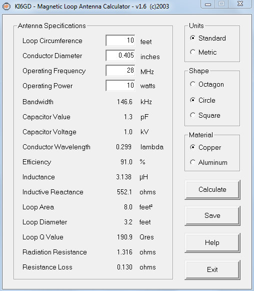
KI6GD Magnetic Loop Calculator This model can be downloaded as an execution file ready to open after download. It is easy and interesting to use as it also illustrates "what-if" situations. Operating Frequency is limited to 1-30 MHz. Conductor Diameter of LMR-400 coax is .405 inches. Loop circumference, shape, and frequency affect antenna Efficiency. This model calculates greater antenna efficiency at 10 meters than at 20 meters with the loop circumference at 10 feet. The author has included calculations for octagon, circle, and square loop configurations. Antenna efficiency varies slightly with each loop configuration. Antenna diameter is calculated which is helpful for forming any conductor into a circle. The circle configuration has the best efficiency compared to octagon and square.
Coupling loop Ian Scott (ZL4NJ) describes three general strategies for impedance matching:
The Faraday coupling loop configuration was used for impedance matching in this project. Circumference of the Faraday loop is 1/5 of the main loop circumference. With 10 feet chosen for the main loop circumference, a circumference of 2 feet was used for the Faraday coupling loop. Frank Doerenberg (N4SPP)
suggests
five configurations for constructing the coupling
loop. Configuration #4 was choosen due to its simplicity and ease of construction.
This configuration does not split the coax at any point as the other
configurations do.
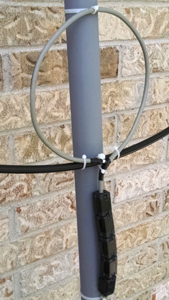
RG-8X coax was used for the coupling loop. The 2-foot circumference was formed into a circle with an 8-inch diameter. Ferrite beads were added to reduce or eliminate common mode currents.
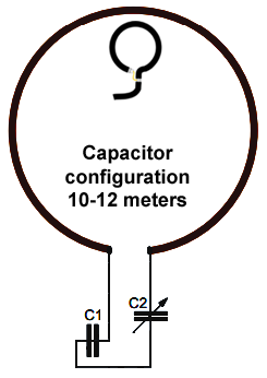
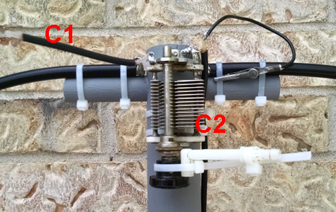
Capacitor - Variable and Fixed An old but very good variable capacitor was purchased on eBay. The capacitance range was not posted, nor did I have a capacitance meter to measure it. Series and parallel fixed coax capacitors were used to compensate for the unknown variable capacitor C2. RG-58/u was initially used and has approximately 25-28pF capacitance per foot. RG-8X was later used and has approximately 30pF capacitance per foot.
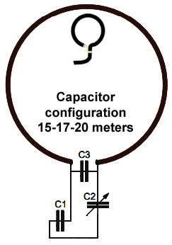
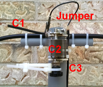
Fixed coax capacitors C1 and C3 were shortened until the desired capacitance was obtained based on SWR. 1/4-inch center insulation was allowed to extend beyond the braid at the open end to prevent arcing due to high voltage levels. Each inch removed equals 2.5pF. When changing bands, the first step is to tune C2 for loudest background noise, check the initial SWR, and then adjust C2 slowly for lowest SWR.
This indoor small magnetic loop antenna was an interesting antenna to build and use. Many contacts were made on 20, 15, and 10 meters using PSK-31 and 10 watts. Propagation was not favorable on 17 and 12 meters immediately after construction when testing, but a good match was obtained on both bands. Initial tuning on any band involved tuning the variable capacitor for loudest background noise and then checking SWR. Tapping the plastic handle lightly in either direction would eventually produce an SWR less than 2:1. The built-in antenna tuner on the Icom 703-Plus was used for bandwidth after obtaining an SWR less than 2:1. Using an internal or external antenna tuner can be used if needed for transceiver matching.
Additional Reading |