|
A small magnetic loop antenna is an easy and cheap antenna to build. It can be used indoors or outdoors with near equal results. Stateside and DX contacts have been made with an indoor small magnetic loop running 3-50 watts using CW, PSK, JT65, and FT8 modes on 10-40 meters. Using wide-spaced variable tuning capacitors allow for higher power with no arcing. The two small magnetic loops
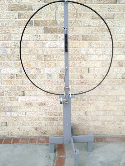
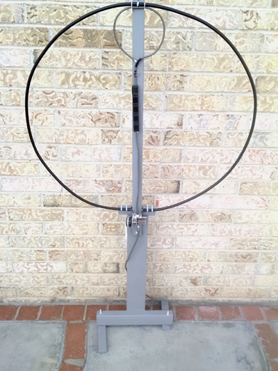
described in this article are for (1) fixed operation using a 9-foot
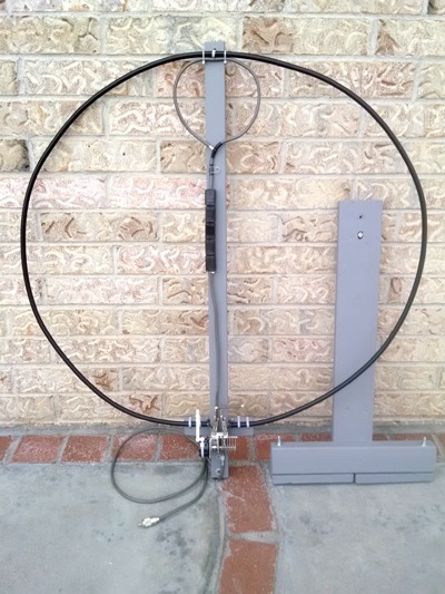
circumference loop with a fixed stand, and (2) portable operation
using an 8-foot circumference loop with a break-down stand. Background The basic configuration of an inductive-fed small magnetic loop consists of the main loop, coupling loop, and a capacitor - fixed or variable. This antenna requires no grounding or counterpoise since it is a resonant circuit. Performance is not limited by low height.
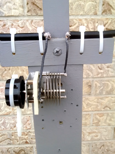
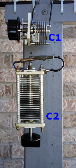
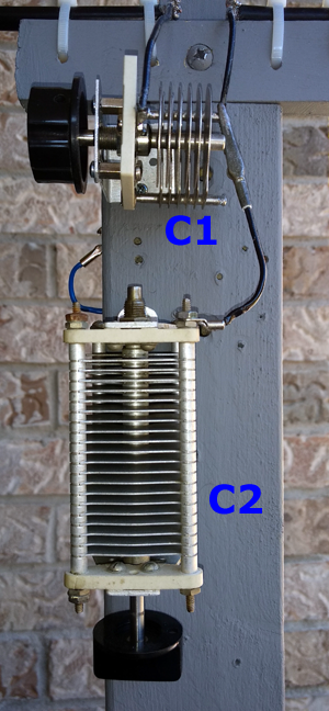
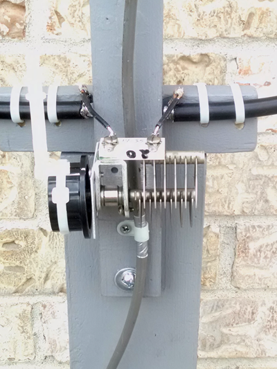
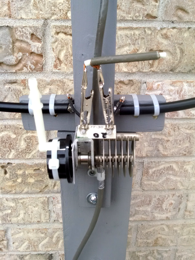
Main loop: The main loop can be configured as an octagon, circle, or square. Circle configuration is the most efficient, but all three configurations will work. Diameter of the loop conductor is generally 3/8 inches or greater. RG-8 (model LMR-400) coaxial cable was chosen over copper tubing since it is easy to work with. LMR-400 requires no tools for bending into a circle, has a solid center conductor for strength, and the two-layer outer conductors (braid plus foil shield) insure less loss due to continual conductivity. The center conductor is generally not used, but G8ODE illustrates that the center conductor can be shorted to the coax shield in his QRP loop tuner. Capacitor: The fixed or variable capacitor tunes the loop antenna for lowest SWR. The capacitor is located at either the top or bottom of the main loop, but always opposite the coupling loop. An antenna tuner may also be used for obtaining lowest SWR. Coupling loop: A coupling loop
is used for feeding the magnetic loop inductively. N4SPP suggests
five configurations for constructing the
Faraday coupling
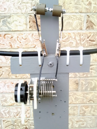
loop. Configuration #4 below was chosen due to simplicity and ease of construction.
The coax is not split at any point as illustrated in the other
configurations. RG-8X coax is used for the coupling loop.
Radiation pattern: Maximum radiation of a loop is off the vertical ends with a figure-8 pattern similar to a dipole antenna. Theoretically, a loop can be rotated using the null side to reduce QRM. In practice, contacts have been made off the ends and null side without a need to rotate the loop.
Tuning: Tuning is simple, but touchy due to hand and body capacitance from being too close to the loop and variable capacitor. Try to tune at arms length.
Fixed Operation
Portable Operation
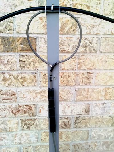
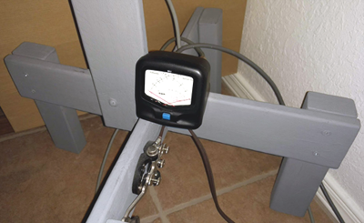
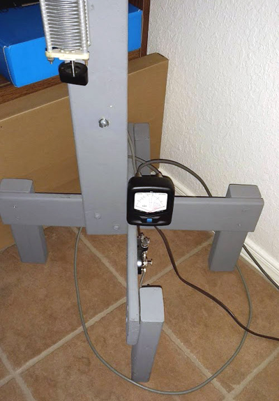
Tuning the Loop Resonance is obtained by changing the fixed capacitors and/or adjusting the variable capacitors for lowest SWR. Since my stand-alone or built-in SWR meters were difficult to accurately view from 5-8 feet away from the rig, I decided to place another stand-alone SWR meter at the base of the loop. I have used this method in adjusting HF mobile antennas instead of running back and forth from front seat to rear bumper. A J-38 telegraph key was used to key the transmitter using 10 feet of zip cord. Alligator clips were soldered at the transmitter end to clip to the existing paddle or straight key terminals. The SWR meter is shown mounted (actually glued) at the base of the 9-foot circumference loop.
Summary Both small magnetic loop antennas were interesting to build and use. Five magnetic loops have been built, but the two described in this article have been the most successful. The magnetic loop is placed at least 5 feet away from the operating position with the null side facing the operator. Many stateside and DX contacts have been made on 40, 30, 20, 17, 15, and 10 meters using CW, JT65, FT8, and PSK31 modes. Propagation has not yet been favorable on 12 meters from my QTH. Power used for both loops ranged from 3 to 60 watts during general QSOs. Full CW key down was tested using 100 watts for 5 seconds. No arcing resulted due to wide spacing of each variable capacitor. The indoor small magnetic loop might be an option if an outdoor antenna is not possible. Working ZL3NB (9-foot loop―30w―PSK31) and LW6EUR (8-foot loop―30w―PSK31) using an indoor antenna was very exciting.
Additional Reading |