Small Magnetic Loop Antennas Steve Yates - AA5TB Full article: http://www.aa5tb.com/loop.html I have been experimenting with small (generally less then 1/10 wavelength circumference) transmitting loop antennas in the HF bands since the 1980's. The ARRL Antenna Handbook's equations helped me put a little design effort into these antennas so that I could make them work the way I wanted them to work. Small transmitting loop antennas are very useful when space for a full size antenna is limited. When care is taken during the construction to minimize resistive losses, performance can be very respectable. Users of this antenna, including the military, have reported very good results even when mounted close to the ground. I have used small transmitting loop antennas close to the ground, leaning up against wooden fences, and indoors with very acceptable results. Beware however that the fields near this antenna are very strong so do not plan on using any more then QRP power levels unless you can get the antenna up and away from people. This type of antenna is ground independent in regards to not needing a separate return to function. Like all antennas the further you get it from the ground or the better the quality of the ground the lower the ground losses will be. A small transmitting loop antenna will perform well even close to the ground when mounted vertically and will exhibit useful sharp nulls in the azimuth pattern. When orientated horizontally, the azimuth pattern will be omni-directional but will have an elevation pattern similar to a horizontal dipole at the same height with the exception of a constant null at the zenith. You can have any two of the following antenna parameters - you cannot have all three.
Small transmitting loop antennas sacrifice bandwidth for small size and efficiency. The more efficient they are, the more narrow the frequency range in which they can operate. If you have built a wide bandwidth, small antenna then you cannot have good efficiency. You have probably built a dummy load! If you do seem to have all three then your feedline is part of your antenna system and you don't really have a small antenna. The practical upper frequency limit for a true and efficient small loop appears to be about 60 MHz. The loops I have built for higher frequencies exhibit the useful sharp nulls and very narrow bandwidth but even for very thick conductors the loss due to the skin effect is just too high for transmitting applications. The UHF loop described later this page is very small and was made as efficient as possible without resorting to silver plating or superconducting construction yet it still gets very hot with only 10 watts of RF at 445 MHz. Loops at the upper frequencies may still be useful for receive only applications such as radio direction finding or use as a front-end bandpass filter.
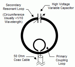
Construction of a small loop is pretty straight forward. Choose the desired loop diameter based upon materials available and performance desired. The larger the loop diameter, the greater the efficiency. If it is made larger then about 1/10 wavelength in circumference it will no longer be classified a small loop and its radiation pattern will begin to change. Choose a conductor with as large diameter as you can find and it preferably should be copper (or silver). This is to keep the resistive losses low. The conductor does not have to be solid. I once used some 3/8" Heliax coax for the main loop and had good results. Heliax cable uses a corrugated copper tube for the shield. A common idea is to use a thick braid to connect the capacitor to the main loop but be cautious if you do this. I once used a braided conductor to connect from the main loop to the tuning capacitor and the braid actually got hot! My experience is that losses are actually higher in braid at high RF currents then for solid wire or tubing. Choose a capacitor value that will resonate the loop to the desired frequencies of operation. The capacitor is the most difficult part of constructing this type of antenna. Because of the very high Q, most available capacitors will start arcing over at powers as low as 10 watts. Remember that even with only a few watts of power, there can be thousands of volts across the capacitor and several amps of current through the capacitor (not necessarily in phase, no free power!). Losses in conventional capacitors can be high due to the several milliohms of resistance found in their brush contacts and non-welded vanes. For this reason you should try to find or build a split stator capacitor of some sort with welded vanes. The idea is to not have RF current flowing through any moving and/or mechanical contacts. The spacing of the plates will have to be large unless low power is used. If you are using QRP power levels and all you can find is a single stator/rotor capacitor go ahead and use it. Just be aware that the losses will most likely be greater in this type of capacitor. I have made small loop antennas using conventional broadcast receiver capacitors and they worked well for QRP use although I know their performance could have been better. To couple energy into the loop several methods are available. By far, the easiest method is to simply construct a coupling loop as indicated in the sketch. No physical connection is required between this coupling loop and the main loop although no harm will come if you want to connect the bottom shield of a sheilded coupling loop to the bottom of the main loop. For capacitive shielding properties, you may want to construct a shield coupling loop. This will supposedly ensure that only magnetic coupling occurs between the primary and secondary loops. RF probe measurements have indicated no common mode currents on the feed line in both cases and the antenna patterns are well defined in both cases so balance does not seem to be problem. To create a shielded coupling loop simply take the end of the feed line coax and loop it back upon itself to form the desired loop dimensions. Where the loose end meets the coax again, strip and solder both conductors of the loose end to the shield of the coax. At the top of this coax loop, cut the shield and produce a small gap all the way around the coax. The shield should be totally separated at this point. This style of
shielded coupling loop will make the entire antenna system
unresponsive to electric fields. If the small coupling loop is made
slightly larger than is necessary then one can adjust the coupling
by rotating the small loop inside the larger loop. This makes for a
very precise method of adjusting the coupling.
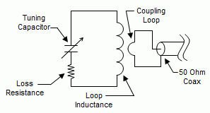
Magnetic Loop Antenna - 10-17 Meters Full article: http://homepage.tudelft.nl/9e08q/magneticloop/ Magnetic loop antennas are very compact HF antennas. If properly build they can be used for transmitting. There are already many good theories about them so i will keep this part of the story very short. Information can be found in the ARRL Antenna book, Rothammels Antennenbuch (German) and on the internet. The schematic diagram of the antenna is shown right here. You can click on it to see a larger version. The main loop is an LC circuit where L has just 1 big turn. The coil acts as a radiator and the capacitor brings the circuit into resonance. The current distribution is equal in the whole loop. The main loop is inductively coupled to the transceiver with a smaller loop. This coupling loop can be made in various ways but always has a diameter which is 5 times smaller than the main loop and is coupled to the transceiver directly with 50 ohm coax. The radiation resistance of the antenna is very low and therefore it's very important to keep the DC losses in the range of milli-Ohms. Practical construction details are described in the next paragraph. First experiment The loop has a diameter of 75 cm and is made of 12 mm Copper tubing obtained from the local Do-It-Yourself shop. The main loop is made of 1 piece to keep the dc resistance very low. The split stator capacitor was obtained from the military dump and has 2 sections of 100pF - 1mm spacing in series, resulting in 50 pF - 2mm spacing. The loop is soldered to the fixed plates on both ends. Never use rotator contacts because the voltage at the capacitor will be several kV's and there will flow high RF currents even at QRP level. The coupling loop has a diameter of 15 cm and is made of RG58 coax. It is called a shielded or Faraday loop. You can click on the image right of this text for the construction details. It is not connected to the main loop and should be placed opposite of the tuning capacitor. The loop is coupled directly to the transceiver - no antenna tuner is needed. The loop needs to be tuned carefully and the practical bandwidth varies from 20 kHz on 17m to 100 kHz on 10m. Coarse tuning is done by searching a noise peak while receiving. Next tune for the lowest swr with low power. At last increase transmitting power to the desired level. The SWR is below 1:1.5 on all bands. Results The antenna works properly with 50 watt rf
without sparks at the tuning capacitor. Within 2 weeks i made some
qso's on 12 and 17 m cw with 50 watts. Distances up to 10000 km
(several times) were no problem and reports varied from 559 to 599.
The antenna is still inside the house just under the rooftop at 8
meters above the ground. Propagation was moderate to good. With 50
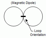
watts cw, there is no BCI or TVI at all. Magnetic Loop Antenna FAQ Considering the controversy any ham antenna conversation can generate, I thought it was important for me to write down some of my opinions on and about Magnetic Loops. People are going to ask these questions over and over again, so I might as well save them the trouble upfront. Some of these observations are based on real world testing, building, and daily use of many magnetic loop antennas. So please find this FAQ a resource for your exploration and in no way a dogmatic listing of ideas. Some of the information you find here is simply what I have found to be the case when tested by me. 1. What is a Magnetic Loop? A Magnetic loop or STL (small transmitting loop) is a large coil with a capacitor added to bring the system to resonance. It is unlike a large resonant loop (more common) in that the loop size is smaller than 1/4 wavelength and does not resonate on its own.
The loop is brought to resonance by attaching a capacitor to the two open ends of the loop. The loop is tuned by a changing the value of the capacitor. An increase in capacitance will bring the resonance of the loop lower in frequency, a decrease in capacitance will make the loop resonate higher. An excellent resource for more in depth information is the ARRL Antenna Book, section 5 (there is a lot of good info, but don't believe everything you read!). 2. How well does it perform compared to other antennas? A Magnetic Loop's performance seems to be dependent on construction, placement above ground, and other factors. A generalization of performance would place it a bit below that of a dipole, and in some instances exceeding the performance of a dipole. It usually will far surpass the performance of most mobile antennas, and other compromise configurations (however, there are always exceptions). 3. Why do you build your loops as squares instead of circles or octagons? Circles are more efficient by about 10%. But they are harder to make when your working with one or two inch copper. I would rather just build the loop a little bigger to gain back the loss. For instance, according to KI6GD loop modeling software, it only takes a extra foot and half of circumference or an extra half inch of diameter of pipe to gain back the lost efficiency. Squares are easier to make and have less solder joints than octagons. 4. Is copper better than aluminum for loops? Absolutely and for the most part. It has over a 20% difference in efficiency according to some modeling software. More efficiency equals more performance. It's also a lot easier to solder, and can be found at your local hardware store. However, aluminum is far lighter. It's a trade-off. I would hate to know what my 12 ft x 12 ft loop with 2 inch diameter pipe would weigh if it was made out of copper instead of aluminum. Please remember, my aluminum loop works great. 5. How important is loop circumference and size of the conductor diameter? Loop circumference relates directly to efficiency and performance (also, loop image: see below). The larger the circumference of the loop, the better your loop will work -- however, if you exceed 1/4 wavelength, things seem to get mysterious. It's a balance, I try to get about 85-90% of the wavelength in circumference, and that seems to be the magic number. However, I'm not making any definitive statements because I have found loops above 1/4 wavelength that seem to work well. There are other factors that effect the total loop size, and that is loop pipe diameter. I have built loops that were 16 feet in circumference and made out of 2 inch copper. The loop worked poorly on 20 meters (where 16.5 feet would be 1/4 wavelength), and worked better on 40 meters. What I assume is that if you use pipe that exceeds a certain size, the total loop size (not circumference), but total loop image, in other words the electrical size is too big for the intended frequency -- maybe. You end up exceeding the wavelength limit and the loop starts to self resonate (according to some people). I have built half inch copper 16 foot circumference loops that worked much better on 20 meters than the 2 inch copper version. So be careful when building your loop and understand that pipe diameter plays a part in its performance. What I would propose is that my 80 meter loop that is 12 feet by 12 feet is in fact larger electrically (or in image) larger than its 48 feet circumference because of the 2 inch pipe size. I believe that if I would have used smaller pipe, the loop would not have worked so well on 80 meters. This is conjecture. I would compare this to the effect of a fat dipole or cage dipole. The thicker the diameter of the wire the shorter the length of the total dipole. It seems to make sense that the thicker the diameter of the conductor, the larger the total loop image will appear electrically. However, one thing I and others have noticed is that if you build a loop for the low bands, make sure the pipe is thicker rather than thinner. I would suggest two inches and above, this seems to deliver the best results. 6. Do I really need to solder or weld all the joints on a loop? According to almost all the literature I have seen on loops, all connections must be soldered or welded. Please read on because I do not believe it's that simple. It appears that mechanical connections create resistance in the conductor which cause major losses in efficiency. It is interesting to note that all the loop articles I have seen and read do not discuss mechanically built loops, only welded versions. I myself have built both mechanical and soldered loops and have not found major variations in performance if the mechanical connections are well made. This is purely observational. My 12 foot by 12 foot loop for 80 meters has no welded or soldered connections and works well from my daily observations and anecdotal evidence. Keep in mind, however, that each segment of pipe has a 3 inch taper that slides into the next pipe (and is then bolted together) -- so there is plenty of overlap for each connection. I have also built loops mechanically, tested them for some time, and then soldered them together to see if there would be a measurable change. As of yet, as long as the mechanical connections are well made, there seems to be no measurable difference. These conclusions do not seem to correspond to the general literature of loop making, but I feel it is important to put this information out there for debate. 7. Can I use regular air variables from an old transmatch for tuning? Most loop literature would say that the wiper connections on commonly found air variables are too lossy. Also voltage capacity is an issue. Any capacitor used should be able to withstand high voltages in the 3-4KV range if you are running 50-100 watts. If you are using welded stator or butterfly capacitors with a high enough voltage rating there should be no problem or significant losses. However, high voltage stator or butterfly capacitors with a large capacitive range usually cost about the same as a nice used Jennings Vacuum Variable. I personally use the vacuum variables. A cheap alternative to expensive high voltage variables is the use of coax for monoband utility. Take a good piece of coax, separate the braid from the conductor for a couple of inches and attach each side to each open end of the loop. Use varying lengths of coax to create different capacitance values for tuning. Trim the coax till you reach your desired resonance. This works very well if you don't mind being stuck on one band. You can also change the coaxial stubs when you want to change frequency pretty easily. I have heard opinions put forth that braid in coax is too lossy for good loop performance for capacitors, but I have not found this to be the case at all. 8. How well does a loop made of coax work? When using coax, either the ground braid or the center conductor can be used. Unless you using one inch hardline the diameter of the braid is simply too small for high efficiency. Have I tried it on RG-8U and other types of coax? Yes. Does it work well? In my opinion the answer is no. One inch or even half inch copper pipe will work much much better. I would not recommend this strategy at all since every experiment of this type yielded poorly performing loops. Some opinions believe that the braid in coax is too lossy because it is not one piece of metal but strands of copper with minute gaps between the pieces introducing excessive losses. 9. Does a loop have a gain pattern? A vertically positioned magnetic loop has a figure eight gain pattern along the plane of the loop itself. In other words, think of two donut shaped patterns radiating from the the vertical portion of each vertical side. This pattern creates a null where the two donuts meet in the center of the loop. A loop with its vertical sides placed north and south, will radiate best north and south. The same is true if you rotate the loop east and west. Loops can be placed on rotors and the loop can be turned for best signal strength or it can be used to null out offensive interference. Magnetic Loops also radiate RF at all angles, so they are well suited for both high and low angle reception and transmission. This is advantageous for both high angle NVIS work, and DX. Loops that are mounted horizontally radiate in an omnidirectional pattern and do not share the benefit of a vertical polarization. I would recommend vertical placement. 10. Are loops quieter than other antennas? A lot of literature on loops make this claim. I
have noticed that I do hear less noise than hams I am talking on
many occasions. They complain about it and I don't hear what they
hear . But remember, they may be using better antennas which have
more gain and usually have more noise as well. Another factor could
be the high Q of my loop acting as a filter for more broad band
noise.
G3BGR Magnetic Loop This magnetic loop antenna was used indoors on 7, 10 and 14 Mhz. No antenna matching unit was necessary with a good match obtained on all three bands.
A 10 foot length of 5/16-inch copper tube gives a 39-inch diameter
loop. The gamma match is 12 inches of 1/8-inch wire spaced 1
inch from loop. The ends of the loop are terminated with a
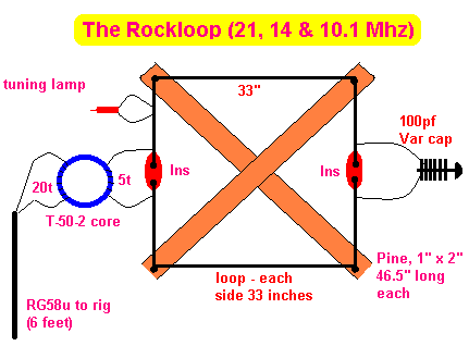
75pf variable capacitor with a 20pf variable to act as fine tuning. The Rockloop  This small loop antenna was described in Sprat 60. It has proven useful to the QRPer, especially where space is at a premium. It is basically a variant of the usual magnetic loop using a toroid balun to get a reasonable match on the three bands. A slow motion drive would prove useful on the tuning capacitor which is a 100 pF air-spaced variable. The lamp is used to tune the loop. Depending on local environment, it may be necessary to experiment with the dimensions of 33" square and the turns on the toroid. The author worked several thousands of miles with QRP using this antenna indoors.
|


